Whenever we are working with AutoCAD Electrical, one of the key features that we have when we are creating our drawings, is the ability to
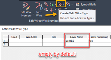
create and assign the custom wire types that we will use throughout our schematic designs. Every time that we create a new drawing, by default the only wire that is going to be available is the WIRES layer which is the generic wire type that the software uses when we first create any type of wire as displayed on Figure.1 in the Create/Edit Wire Type editing window.
Having to manually enter the types of wires that we are going to use is a task that cannot be avoided the very 1st time that we create a drawing, but once we having created the list of wires that we need to use in one drawing, we can reuse them over and over again.
To achieve this we need to do the following:
- Open the Create/Edit Wire Type editing window and click on the icon that says “Import” as seen on Step 1 on Figure 2.
- A window will pop-up asking you to browse to the drawing that contains all the wires information, browse to the desired drawing.
- Once we have selected the DWG another window will pop-up displaying all the wires from that drawing.
- By default all the wires from that drawing are selected and highlighted in black as seen on Step 2 on Figure 2.
- We can pick and choose the wires that we want to import and the click OK to complete the process.

Figure 2To take this one step further, we can standardize the wires that we use with your CAD Manager so we can import that list of wires directly into your templates. To achieve this we need to open the current template as a DWT file, then repeat the exact same process that was described earlier.
Once we have completed importing all the wires we need to re-save the template as a DWT one more time to make sure it will be usable as a template in the future.
This will further standardize the wires that the designers are required to use and remove the guess work by setting the wires at a template level.


