
June 16, 2023
Flow and Pressure Drop Calculations Available in MEP Fabrication Elements
Have you noticed in Revit you have to choose between ducting and piping that supports flow propagation OR ductwork that is modelled for the intent of fabrication?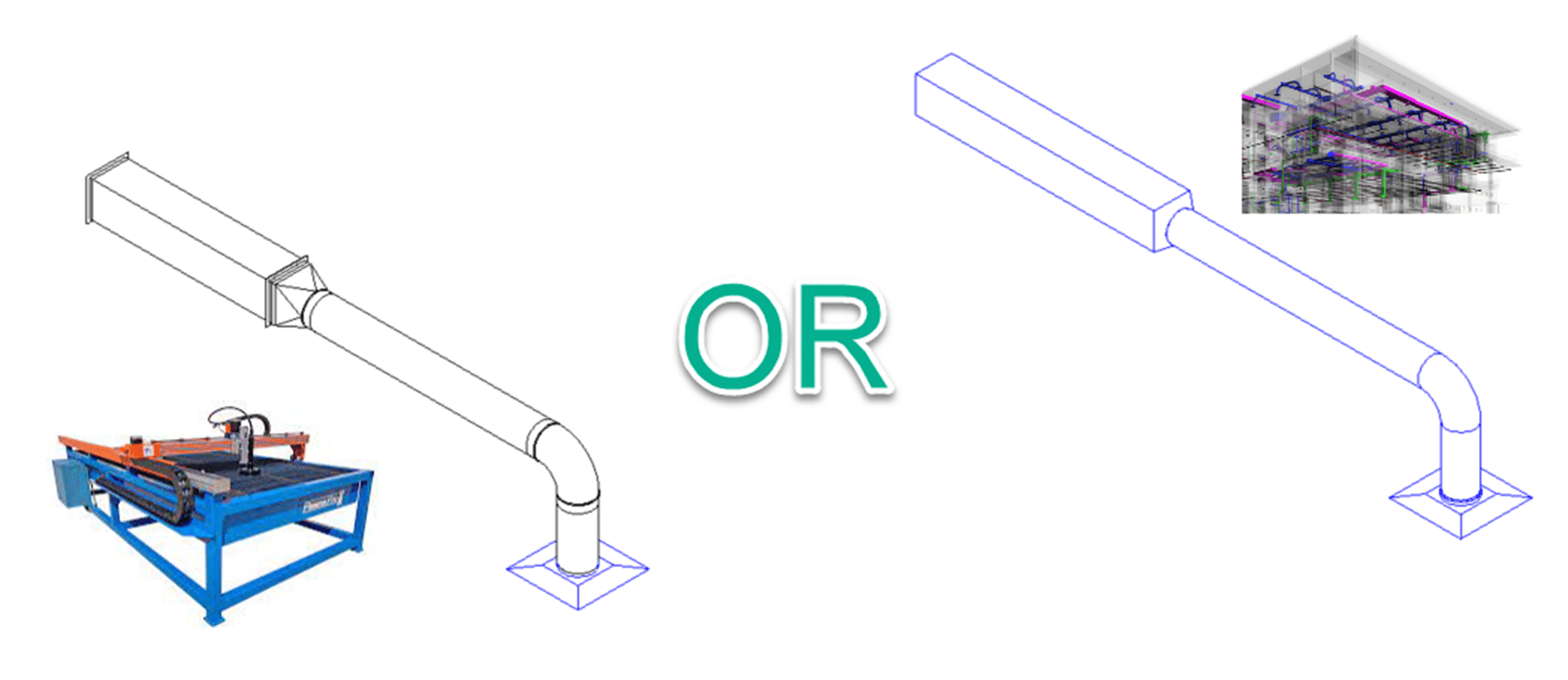
In the 2024 release of Revit, Autodesk has made great improvements related to the fluid flow within fabrication elements, getting us one step closer to the single tool for both design and construction.
Using Ductwork as an example I will show you the new functionality and point to some of the benefits of each approach to modeling in Revit MEP.
Figure 1. Design and Fabrication Ductwork Interchanging
One of the limitations of Fabrication Ductwork since its introduction to Revit in version 2016 has been that, once placed or converted from Design to Fabrication, you lose the design data within the model. No Flow values passed from the Air Terminals, Plumbing Fixtures, Equipment etc into the Fabrication elements. This meant that when the model was passed from the design consultant to the contractor – and they made the change to fabrication parts to enable them to export data out to a cutting table or spooler – they would have to manually calculate future changes in flow values to make sure the ducts were ideally sized.
This differs to the design elements, where the flow, duct size, fluid velocity would all be visible within the design elements, making a change to the ducts dimensions immediately shows up with changes to the velocity, as would a change to the flow value of a downstream connected element.
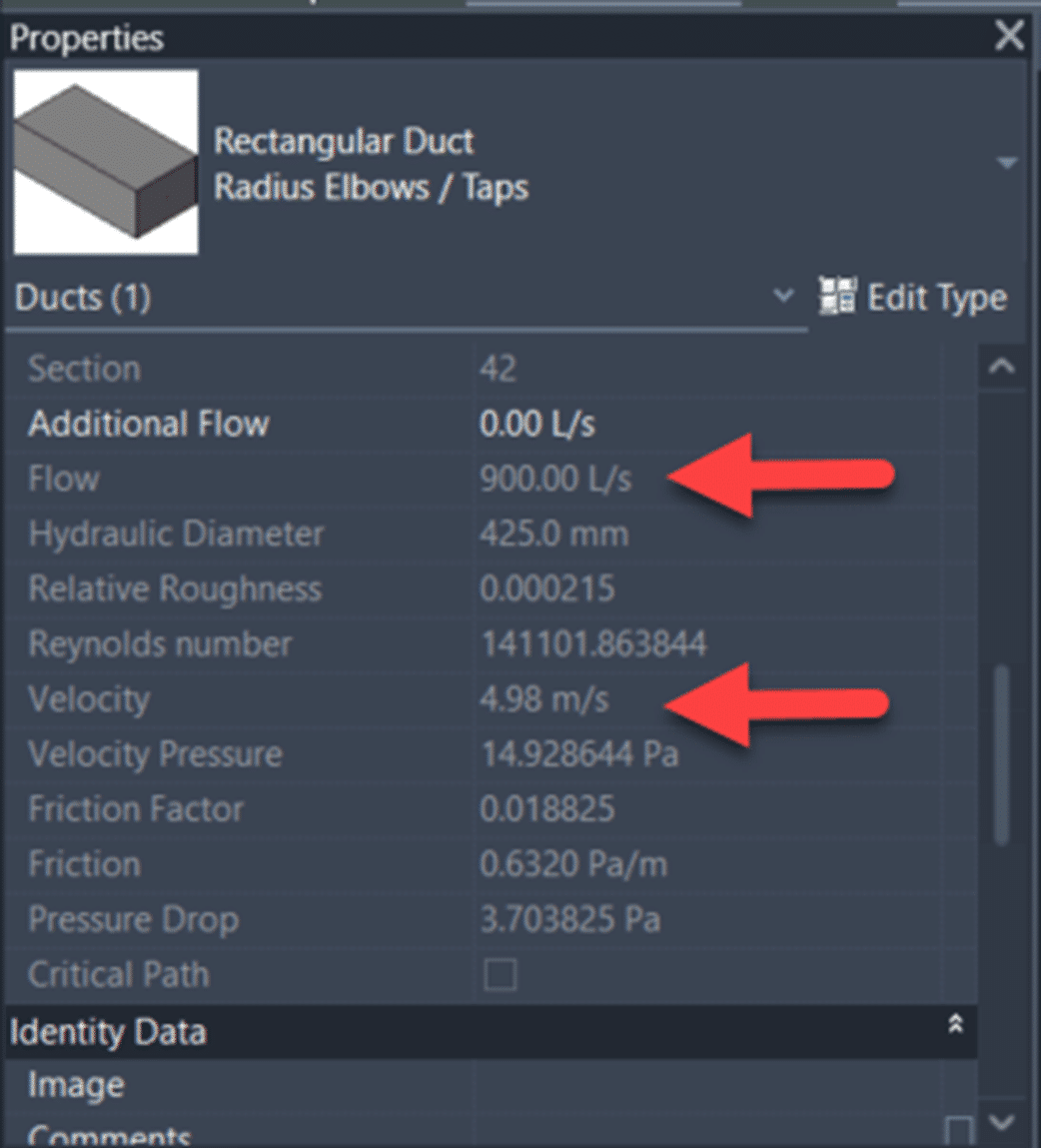
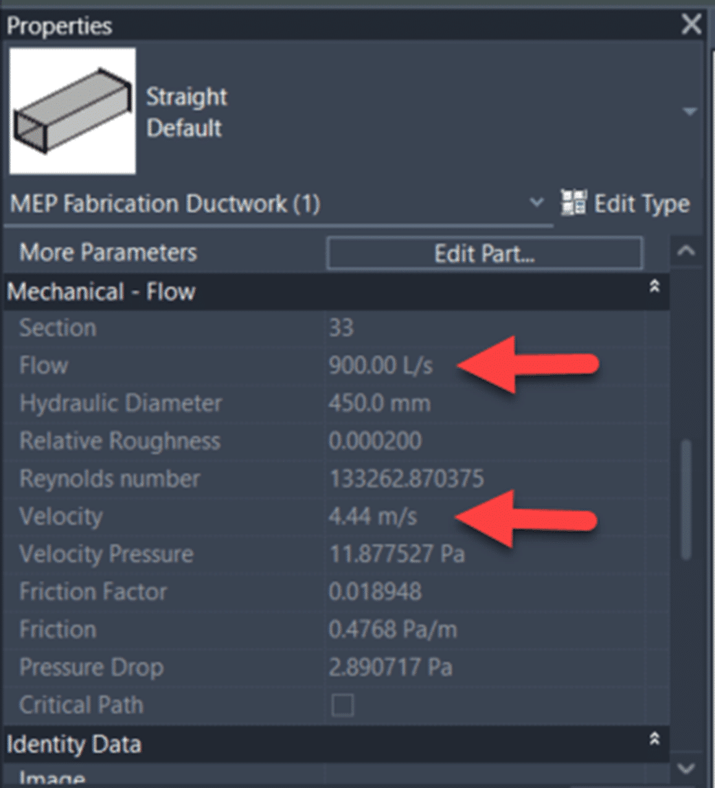
In Revit 2024, Fabrication MEP elements now show all of the same information as the design elements:
For some reason they have neglected to include the simple Duct/Pipe Sizing tool for MEP Fabrication Ductwork, but you can get around this with a ductulator, or some simple Dynamo:

Just kidding (on the simple bit), let me know if you want the Dynamo File, Its by no means complete, but it does some basic sizing of Rectangular MEP Fabrication Ductwork based on velocity, flow and cross sectional area.
Another limitation is that the System Color Schemes do not show up for Fabrication elements, when you place a System Color Scheme into a view to show the Duct Velocity for example, you will see something similar to the below with Design Duct:
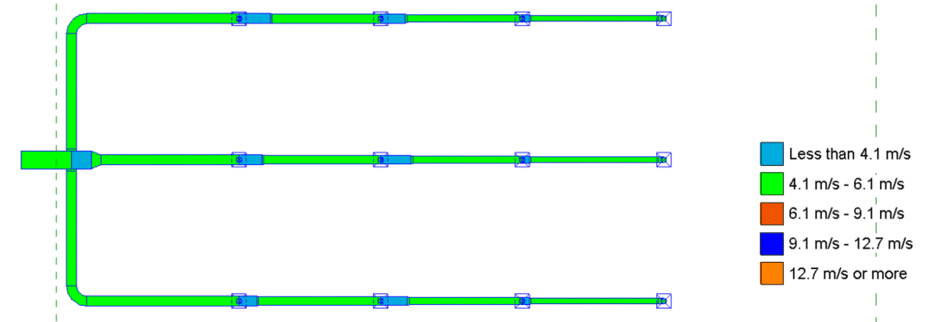
But it has no effect on MEP Fabrication Ducts in the view… So while Design Duct has some knowledge of which systems are passing through it, MEP Fabrication Ductwork would seem to not have been made privy to this information.
So how do we get MEP Fabrication Ductwork showing the flow value from connected Air Terminals in Revit MEP? Follow these steps in Revit 2024:
1. Open Revit 2024.
2. Start a new project based on the new Metric Multi-discipline template.
3. On the Systems Ribbon Tab, Fabrication Panel, click the Fabrication Part tool.
4. Click Settings in the lower right corner of the MEP Fabrication Parts palette.
5. Select the ‘Fabrication Metric 8.0’ Fabrication configuration.
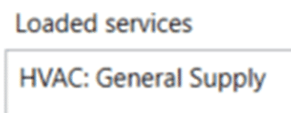
6. Scroll down the unloaded services until you see the ‘HVAC: General Supply’ service, select it and click the Add button to move it to the Loaded Services column.
7. Click OK to exit the Fabrication Settings dialog.
8. On the Systems Ribbon Tab, HVAC Panel, click the Air Terminal tool.
9. Open the L1 – Mechanical view.
10. Select the ‘M_Supply Diffuser : 600 x 600 Face 300 x 300 Connection’ Family Type in the Type Selector and place it at an elevation of 2400 from L1.
11. On the MEP Fabrication Parts palette, select the ‘Multi-Point Routing’ tool.
12. Click on the top center of the placed Air Terminal.
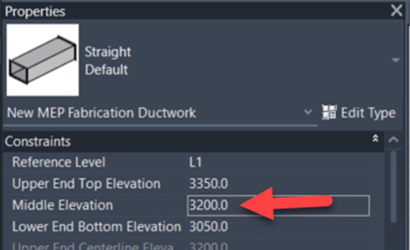
13. Set the Middle elevation in the properties to 3200.
14. Continue to place more MEP Fabrication Ductwork, or finish the command.
15. Select the Air Terminal and note the Flow value on the Options Bar.

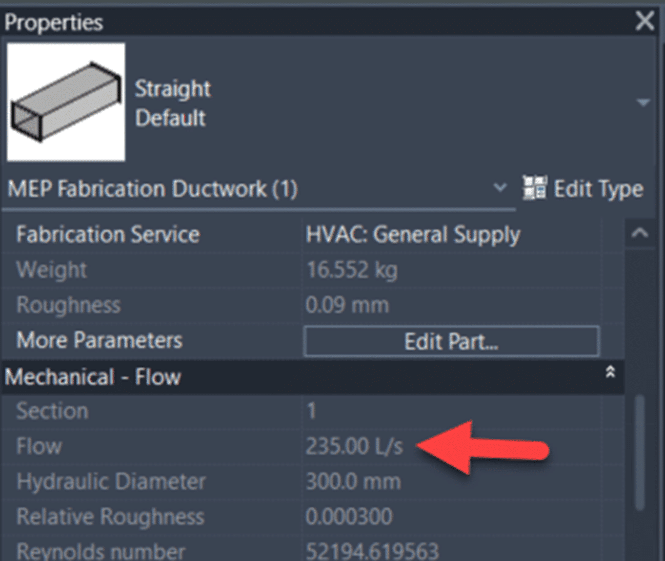
16. Select a piece of the connected MEP Fabrication Ductwork and note in the Mechanical – Flow properties there is a Flow value that matches the flow from the connected elements.
To learn more about Revit, feel free to contact us and one of our representatives will reach out to you shortly.
Related Posts

-
AME Group Success Story
AME Group (AME) is a Canadian mechanical consulting engineering firm delivering complex building design projects across multiple offices. With many project teams working concurrently, consistency in standards, ...
-
Autodesk Construction Solutions New Buying Experience
The New Buying Experience for Autodesk Construction Solutions Simplified Transactions. Smarter Bundles. Same Expert Support. As of March 24, 2025, Autodesk has updated how you purchase and renew Construction ...

- Accruent
- Advanced Manufacturing
- Architecture
- Architecture
- Architecture - Blog
- Assembly Line Automation
- AutoCAD
- Autodesk
- Autodesk Construction Cloud
- Automotive
- BIM
- Blog
- Blog Posts
- Building Design & Engineering Services
- Building Engineering
- Building Engineering - Blog
- Building Product & Fabrication
- CAD
- CAM, CNC & Machining
- Civil 3D
- Civil Infrastructure
- Civil Infrastructure & GIS Services
- Civil, Survey & GIS
- CNC Machining Services
- Construction
- Construction
- Construction Project Lifecycle
- Consulting Services
- Consumer Products
- CPQ & Aftermarket
- CTC Software
- Data Management
- Digital Transformation
- Energy & Utilities
- Engineering
- Engineering
- General
- Government & Public Sector
- Industrial Machinery
- Industries
- Industry
- Industry Topics
- Infrastructure
- Inventor
- KnowledgeSmart
- Manufacturing
- Mining
- News
- Pinnacle Series
- PLM
- PLM & PDM
- Product Lifecycle Management
- Revit
- Sales and Aftermarket for Manufacturers
- Simulation & Analysis
- Software & Technology
- Software Development
- Thought Leadership
- Tips & Tricks
- Visualization
- Visualization & Reality Capture Services