June 17, 2022
How to Create Intelligent Custom Labels with Expressions in Civil 3D
Introduction
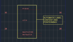
Figure 1 – Dynamically Labelled Basement Elevations

Today we see how we can make labelling much easier and consistently accurate in Civil 3D. “Expressions” are used to create user properties that can automate a lot of label text generation and positioning as well. The expression techniques used here are useful for every kind of custom Civil 3D labels. There are several labelling methods:
- Manual text
- Dynamic block (with attributes)
- Civil 3D Labels (with Expressions)
To set up the easiest labelling workflow, Civil 3D labels with expressions is usually the way to go. We spend a bit of time setting things up, but once it’s setup, it takes little time to do the labelling and even less time to update any changes. Dynamic blocks with attributes and parameters can be just as good, but we’ll save that discussion for another time.
Sample Use Case
In this example, we just want to input the finished floor elevation, how far down the other elevations are, and what lot number we are labelling. We want the label to take care of the rest, including calculations and label positioning.
It can be done for either profile views or section views. A sample DWG is available for download so that you can see exactly how everything was set up. For now, we will go over some high-level notes on what was done.
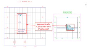
Profile View Implementation
- The finished floor is represented by a TIN surface. The TIN surface is simply defined by a rectangle breakline that’s at the finished floor elevation.
- The actual label is done as a “Lines” label of the FF surface profile, on a profile view.
- To set up a label style properly, we first need some expressions setup- BsmtFlrOffset (-2.9): how many meters down from FF the basement floor is
- BsmtFlr ({Tangent Start Elevation}+BsmtFlrOffset): calculated basement floor elevation
- BtmFtgOffset (-3.25): how many meters down from FF the bottom of footing is
BtmFtg ({Tangent Start Elevation}+BtmFtgOffset): calculated bottom of footing elevation
- ViewScale (2): The viewscale of the profile view. 1:500 = 1000/500 = 2.
- PVExaggeration (10): Vertical exaggeration of the profile view.
- LabelPosition1 (BsmtFlrOffset*ViewScale*PVExaggeration/1000): Y offset used to position the basement floor label. It takes into account the view scale (1:500) and the vertical exaggeration (x10).
- LabelPosition2 (BtmFtgOffset*ViewScale*PVExaggeration/1000): Y offset used to position the bottom of footing label.
- LabelPositionLot (LabelPosition1/2): Y offset used to position the lot number label. Half way in between FF label and the basement floor label.
Sample drawing has four label components:
- FF elevation label: use the “Tangent Start Elevation” property, attached to the feature.
- Basement floor elevation label: uses expression BsmtFlr, positioned by expression LabelPosition1 for its Y offset.
- Bottom of Footing elevation label: uses expression BtmFtg, positioned by expression LabelPosition1 for its Y offset.
- Lot number text label: Since the profile is named with the lot name (LOT 81). Positioned by expression LabelPositionLot for its Y offset.
It takes some initial setup, but once that’s done, all it takes is just applying a Lines label in the profile view and that’s it! Elevations and label positions are automatically calculated and positioned. The only adjustments that might have to be made is editing some expressions to note what elevation offsets, view scale, and exaggeration are used.
Section View Implementation
The implementation is essentially the same as the profile, with a few differences.
- Major Offset label type is used
- Sections actually have “Drawing Scale Conversion” property available out of the box. If the scale is 1:200, “Drawing Scale Conversion” property is 1/200 = 0.005. This makes section labels automatically position correctly for all scales unlike the profile ones!
Conclusion
Civil 3D label expressions can help us set up all sorts of custom labelling that automates calculations as well as label positioning.
It takes a little bit of investment to get used to, but once you set up one or two, it becomes fairly easy and can greatly expand the capabilities of your template. That in turn, helps everyone not only save time, but be more consistent, as dynamic labels help us avoid forgetting label updates as designs change. Navisworks has the ability to open various file types. It can also read embedded data if the proper object enabler is installed. Fortunately, Autodesk has one specifically for Plant 3D. You can download the 2021 version here.
Here’s an example of a Plant 3D model in Navisworks without an object enabler. You can see that some shapes aren’t displayed properly, and it is not reading the embedded data.
Here is the same Plant 3D model with the object enabler installed. All the components are displayed correctly, and the embedded data is being displayed in the properties section.
With the Plant 3D model in Navisworks, the file can now be saved as an NWD file and delivered to external parties. All they need is Navisworks Freedom to view the file, which can be downloaded for free from Autodesk. This is one of many features available in Navisworks. Apart from a robust 3D viewer it can perform tasks such as clash detection and animation.
If you would like to learn more, Navisworks training is available as a supplementary course to SolidCAD’s Plant 3D course curriculum. Please email us at contact training@solidcad.ca.
In the next blog, we will look at how to utilize the Navisworks plug in within Plant 3D. Stay tuned!
- Accruent
- Advanced Manufacturing
- Architecture
- Architecture
- Assembly Line Automation
- AutoCAD
- Autodesk
- Automotive
- BIM
- Blog
- Blog Posts
- Building Design & Engineering Services
- Building Engineering
- Building Product & Fabrication
- CAM, CNC & Machining
- Civil 3D
- Civil Infrastructure
- Civil Infrastructure & GIS Services
- Civil, Survey & GIS
- CNC Machining Services
- Construction
- Construction
- Construction Project Lifecycle
- Consulting Services
- Consumer Products
- CPQ & Aftermarket
- CTC Software
- Data Management
- Digital Transformation
- Energy & Utilities
- Engineering
- General
- Government & Public Sector
- Industrial Machinery
- Industries
- Industry Topics
- Infrastructure
- Inventor
- Manufacturing
- Mining
- News
- PLM
- Product Lifecycle Management
- Revit
- Sales and Aftermarket for Manufacturers
- Simulation & Analysis
- Software & Technology
- Software Development
- Thought Leadership
- Tips & Tricks
- Visualization
- Visualization & Reality Capture Services


