• Bluebeam Actions vs. Adobe

    We Bluebeam Revu users are lucky enough to have access to 2 tools: Edit Action and Capture.

    Edit Action

    This tool does a few things, but many users use it for adding a hyperlink to a selected markup.

    Capture

    This tool allows a user to attach an image to any markup. The image takes up no space until the user clicks it.
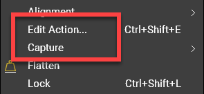
    Usage

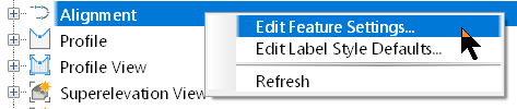
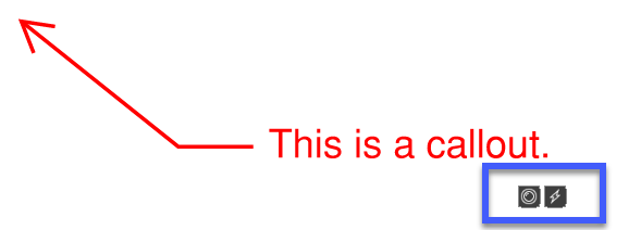
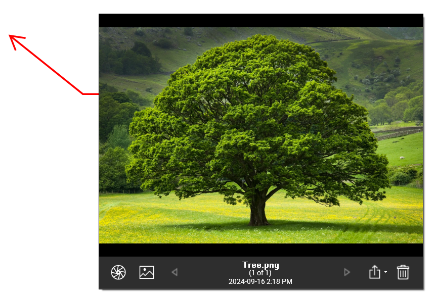
    These 2 tools are accessed by selecting a markup and right clicking. After configuring, they will appear as symbols below the markup. The left one is the image, and the right is the hyperlink. Clicking on the image symbol displays the image in its own temporary interface. Clicking the link opens the link in a new Revu tab.

    Gotcha

    There could be a slight problem though depending on which PDF software your recipient uses. If your recipient uses Bluebeam Revu, there is no problem. These symbols appear and they can be clicked on. If they use any other software, such as Adobe Acrobat, these 2 symbols don’t appear, and they don’t do anything.

    Is there a workaround?

    Workarounds

    1. Flatten the markups (Hyperlink): The link symbol will not appear, but when your recipient moves their mouse over your markup, the link will be clickable.
    2. Flatten the markups (Image): Flattening the markups has no effect on the captured image. Your recipient will have no idea there was ever an image attached to that markup. Sorry, but you’ll have to add the image as a separate markup.

    The other hyperlink tool: Use this tool instead of the Edit Action tool. Adobe users will be able to click these even if you don’t flatten the markups.  You’ll find this in the Tools menu. FYI, this creates a separate markup and it’s in no way linked to any other markup.

    For any questions reach out to your sales rep or contact us at info@solidcad.ca

    Civil 3D 2025.1 Update

    The Civil team at Autodesk has released the latest update to Civil 3D 2025. Click here to see Release Notes and click here for the Online Help page. As usual, the update can be installed via the Autodesk Access app in your Windows status bar, or by downloading the update at your Autodesk Account page.

    Here are a few noteworthy new features:

    Corridor Performance

    If you like to grip-edit corridor regions, but you are apprehensive due to the poor performance and laggy cursor, you’re in luck. I tested a very large corridor with a dense assembly frequency, and I noticed zero cursor lag! Impressive.

    Survey Database

    The survey database is now fully supported in Autodesk Docs.

    Surfaces

    Imagine a surface style that displays only contours, and that style is assigned to a surface. Your goal is to edit the TIN lines or points. In 2025, you’d need to assign a style with those components turned on. Now in 2025.1, these components are automatically turned on after initiating these edit tools.

    Dynamo

    If you’re a Dynamo developer, or you know one:

    • 1100 new nodes have been added.
    • The library has been reorganized.
    • The Dynamo Core has been upgraded to 3.2.2
    • Colour control has been improved.

    For any questions reach out to your sales rep or contact us at info@solidcad.ca

    Civil 3D: Subassembly Composer Tip of the Year

    Good day folks, do we have a tip for you today! If you create custom subassemblies with the Subassembly Composer, you’ll want to read on…

    I’ve created maybe a couple hundred subassemblies for myself and various customers over the years. Some easy and some very involved. In nearly all of them, I’ve wanted to move all or some of the nodes in the flowchart. In this example, I need to move the nodes within the red rectangle.

    It sounds easy, and it is, but only if you know the trick. And many thanks go to my colleague Jae Kwon for pointing this out to me today. Where were you 6 years ago?


    Multiple nodes can be selected by holding the CTRL button while selecting nodes but only one moves.

    Here is the key:

    1. Double click in a blank area. It doesn’t seem to matter where, just double click somewhere, say close to the X in the image.

    2. Select the nodes you’d like to move by holding CTRL and picking them with your mouse. To move all, CTRL+A.

    3. Use the arrow keys (not the mouse) to move them.

    That’s it. Enjoy.

    For any questions reach out to your sales rep or contact us at info@solidcad.ca

    Civil 3D 2025

    Well, it’s that time of year again when Autodesk bestows us with the latest release of their flagship Civil Design application. Read on to see which features speak to this blogger.

    File Format

    This is probably the most-asked question, and I’m happy to say that there is yet again, no format change. We are still on the 2018 format. Good news for everyone!

    Performance

    Performance has yet again been significantly improved across the board in Civil 3D 2025.0.

    Corridors

    There is a new corridor creation dialog box that will allow for more efficient creation of corridor with multiple baselines using alignments and feature lines.

    Civil 3D 2025

    Civil 3D 2025Civil 3D 2025

    Coordinate Systems

    New horizontal coordinate systems have been provided.

    A new vertical coordinate system workflow exists to specify the survey datum. The new command is GEOCSASSIGN.

    Another new system variable named, ENABLEVCSSUPPORT, exists for DEM/GeoTIF files.

    Civil 3D 2025

    Surfaces

    Level of detail tools are intended to increase performance by reducing the amount of data displayed on the screen. Note that in 2025.0 ,two previous commands have been removed: LEVELOFDETAIL and LEVELOFDETAILOFF. These are replaced by object-based settings.

    Civil 3D 2025Civil 3D 2025

    For any questions reach out to your sales rep or contact us at info@solidcad.ca

    Civil 3D: Object Names and Style Descriptions

    Does your company require the use of a specific naming convention for Civil 3D objects? Has it been difficult to adhere to that standard? If so, read on for some tips.

    When an object is created in Civil 3D, it requires a name. This is the naming convention for a new alignment using the out of the box Civil 3D drawing template. It will be named Alignment – (1), the next one will be Alignment t – (2), etc. This name is not very descriptive, and I hope you’re using something better than this already!

    Here is an example of a company’s strict naming convention.

    1234-C-Granville-ALG

    • 1234                     =             project number
    • C                            =             civil
    • Granville              =             road name
    • ALG                       =             alignment

    Users must refer to a naming standard, often a PDF document somewhere on the network, and this can take time. Under pressure, users sometimes skip the formalities and use a non-standard name. We must make it as easy and fast as possible for them.

    Why not embed this standard into the drawing template itself so users won’t need to open another file? Here is how this could be done directly in your Civil 3D drawing template. The users’ responsibilities would be to edit the mixed-caps data and leave the ALL CAPS data.

    Prompting the user with the information they need when they need it will help to ensure better efficiency and (potentially more important) reduce the chance that they use non-standard names. This can be done for all relevant Civil 3D objects in the Settings tab by:

    • Editing the Feature Settings for the object in question.

    • Configuring the name template.

    • Clearing any child overrides so all alignments get named properly regardless of the command used.


    While we’re on the subject, it can be beneficial to include a good description with styles so that users are prompted when or why to use a style. I try not to have make the description so long that my users need to scroll to see the entire thing. They won’t! Make it concise.

    Civil 3D: 2024.3 Update

    Civil 3D 2024 has a new update: 2024.3. You can use Autodesk Access to install it or download it from your Autodesk page.

    Here are the notable enhancements.

    Civil 3D: 2024.3 Update

    • When creating a new corridor, expect to see this new dialog. It allows for the creation of multiple baselines right at the time of corridor creation. For large corridors, this could be a significant time saver.
    • In that same new dialog, feature lines can be more efficiently chosen by filtering based on criteria such as Name, Style, Layer, and Site.
    • Assign alternate assemblies in Corridor Properties for multiple baselines and regions simultaneously.

    Civil 3D: 2024.3 Update

    • The Dynamo Core has been updated to version 2.19. Note, that this can cause issues with Dynamo scripts created prior to 2.19…
      “if you have no nodes set as “Output”, nor a Slider or Boolean Input, it will never show your Inputs in the Dynamo Player.”
      “Adding a node as an Output will “solve” this issue”

    In the API, Added the ability to call the API to export C3D objects to the ArcGIS FileGeodatabase to automate workflows from C3D to ArcGIS.

    Mastering Point Clouds in Civil 3D: A Three-Part Guide to Efficiency: Bonus Part

    This is a bonus article in the Point Cloud series. Click to view: 

    Article 1 

    Article 2 

    Article 3 

    With all this talk about decimation and removing many of those original points in the cloud, how does one know if they’ve removed too many points? Here is how I do it. 

    • Insert the point cloud into Civil 3D.
    • Make a surface from the original point cloud, but only a small subset, so it’s not too big.

    • Make a surface from the decimated classification using the same red border as above. This so you can tell how many points are used for each surface within that area. 
    • Make an alignment and profile sampling both surfaces and have a look. The blue is the original, the red is the decimated cloud. Some of it is bang on and some of it isn’t. You get to decide if you have decimated too much.

    Are there any other ways to decimate that are better? VRMESH and Pix4D are expensive applications that do this, but I have limited experience with them. Civil 3D, however, has one more trick up its sleeve. 

    • Make a new surface and paste the original point cloud surface into it. Yes, the big one, but remember that it’s only using the points within the red border. 
    • Use the Simplify Surface editing tool. The highlighted number is where you can experiment. The bigger the number, the more points will be removed.

    • Sample this new surface in the profile view with the other 2 and compare. The purple profile was created with this new surface. That surface contains about the same number of points as the one created using the decimated cloud from Recap. It is closer to the original.

    What does this mean? Is Civil 3D’s Simplify Surface tool better than Recap’s “Intelligent Decimation”? In my experience, I find that yes, it can give me a better result. But not always. Even in this same dataset, there are areas where the decimated cloud is closer to the original. The red line below. 

    Here is my philosophy. This works best for me. Your mileage may vary depending on your point cloud. 

    1. If a cloud has 80 million points, it is more efficient to decimate it using Recap before it ever comes into Civil 3D. 
    1. Decimate in Recap, but maybe not as much as you would like. E.g., if I think  1 million points is the right number for my Civil 3D surface, I will decimate to 2 or 3 million. 
    1. After modeling the surface, use the Simplify tool to get the surface down to that 1-million-point mark, or whatever your intended number is. 

    Click here to download the sample files. 

    Mastering Point Clouds in Civil 3D: A Three-Part Guide to Efficiency: Part 3

    Most survey and design firms these days rely on point cloud data to some degree. It is often faster, easier, and safer to survey using aerial or ground-based scanners compared with traditional survey methods. 

    “But these clouds clog up my Civil 3D drawing when I make a surface.” You say. I’m here to tell you that they don’t have to! The dataset is always huge, tens or even hundreds of millions of points. When the deliverable is a surface model in Civil 3D, 3 things must happen. 

    This is the third and final in a series of three articles outlining how Autodesk Recap and Civil 3D are used to carry out these tasks. Click here for the first article in this series. Click here for the second. 

    Task 3: Import to Civil 3D and model a surface. You may already know this step, but since Recap has been used to classify and decimate the points, there is a new task in Civil 3D. 

    Once the point cloud has been attached, all the points will show, and it seems logical to go here and ensure that ONLY the decimated points (Key) are visible so we can model the surface using only those points. 

    Yes, only the Key points are visible, but when we try to model the surface, Civil 3D is using all 15 million of them, not the 10,000 that was specified during the decimation process. Autodesk is aware of this “defect”. When or if it will be rectified is unknown. 

    But don’t fret, there is a workaround. 

    Turn on the map Workspace (MAPWPACE) and create a new layer from the point cloud. 

    Filter the Key points in that new layer. 

    Then create the surface normally. Only the Key points will be used. 

    Stay tuned for the BONUS article… Yes, you read that right. There is one more. 

    Mastering Point Clouds in Civil 3D: A Three-Part Guide to Efficiency: Part 2

    Many contemporary survey and design companies now utilize point cloud data to a certain extent. Surveying through aerial or ground-based scanners is frequently quicker, more convenient, and safer compared to conventional survey techniques.

    “But these clouds clog up my Civil 3D drawing when I make a surface.” You say. I’m here to tell you that they don’t have to! The dataset is always huge, tens or even hundreds of millions of points. When the deliverable is a surface model in Civil 3D, 3 things must happen. 

    This is the second in a series of three articles outlining how Autodesk Recap and Civil 3D are used to carry out these tasks. Click here for the first article in this series. 

    Task 2: Decimate (thin) the data. Reduce the number of points to a number that Civil 3D can use. Attempting to model a surface using 80 million points is an exercise in futility! 

    Recap 2024.1 can do this! There are a couple of options; I prefer the second. I like to dictate the number of points that will exist in the decimated cloud. Recap will “intelligently” decimate the cloud so as not to remove too many of the important points. 

    If you have any more questions about Civil 3D points clouds please contact us at info@solidcad.ca

    Civil 3D points clouds

    Civil 3D points clouds

    There will be a new classification in the Project Navigator. 

    Civil 3D points clouds

    And the decimated points will be coloured magenta. 

    Civil 3D points clouds

    Click here to download the sample files. And stay tuned for the third article…

    Mastering Point Clouds in Civil 3D: A Three-Part Guide to Efficiency: Part 1

    Most survey and design firms these days rely on point cloud data to some degree. It is often faster, easier, and safer to survey using aerial or ground-based scanners compared with traditional survey methods. 

    “But these clouds clog up my Civil 3D drawing when I make a surface.” You say. I’m here to tell you that they don’t have to! The dataset is always huge, tens or even hundreds of millions of points. When the deliverable is a surface model in Civil 3D, 3 things must happen. 

    Unfortunately for you, the reader, you’ll need to wait for the whole story as this is only the first in a series of three articles outlining how Autodesk Recap and Civil 3D are used to accomplish these tasks. 

    Task 1: Isolate the ground points. Points that do not fall on the ground such as buildings, trees, and overhead power lines and their poles must not be used to model a surface. 

    Recap 2024.1 can do this! It’s easy as there are only a couple of options to choose from. Really, in my experience, the default option is often the best. 


    There will be a new classification in the Project Navigator. 

    And the ground points will be coloured brown. 

    Click here to download the sample files. And stay tuned for the second article… 

    If you have any more questions about Civil 3D points clouds please contact us at info@solidcad.ca