fbpx
  • Bring your designs to life in Lumion 11.5

    This story was originally published by Lumion on the Lumion Blog.

    With Lumion, you can render more than a building. Render your client’s dream home, render a story about design that moves emotions, render the space where life happens.

    A building begins as a structure. Walls. Floors. Roofs. Windows and doors. All expertly crafted into a beautiful arrangement of form and function.

    When looking at the 3D model, however, you might feel as if something is missing. Maybe it doesn’t capture the energy and atmosphere of the space and its surroundings. Perhaps it doesn’t ignite emotions or make you want to be there. Whatever it is, there’s something about life that’s just not easy to show in CAD.

    With Lumion, you can bring your vision to life and tell a richer, more immersive story about the design’s role in the real world. A story that sparks imagination and helps clients fully visualize how life could unfold within those four walls.

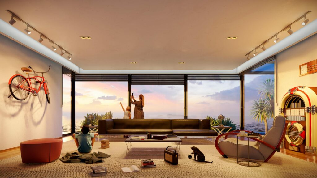
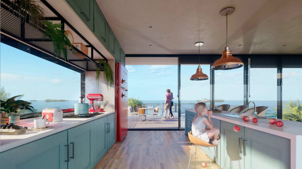
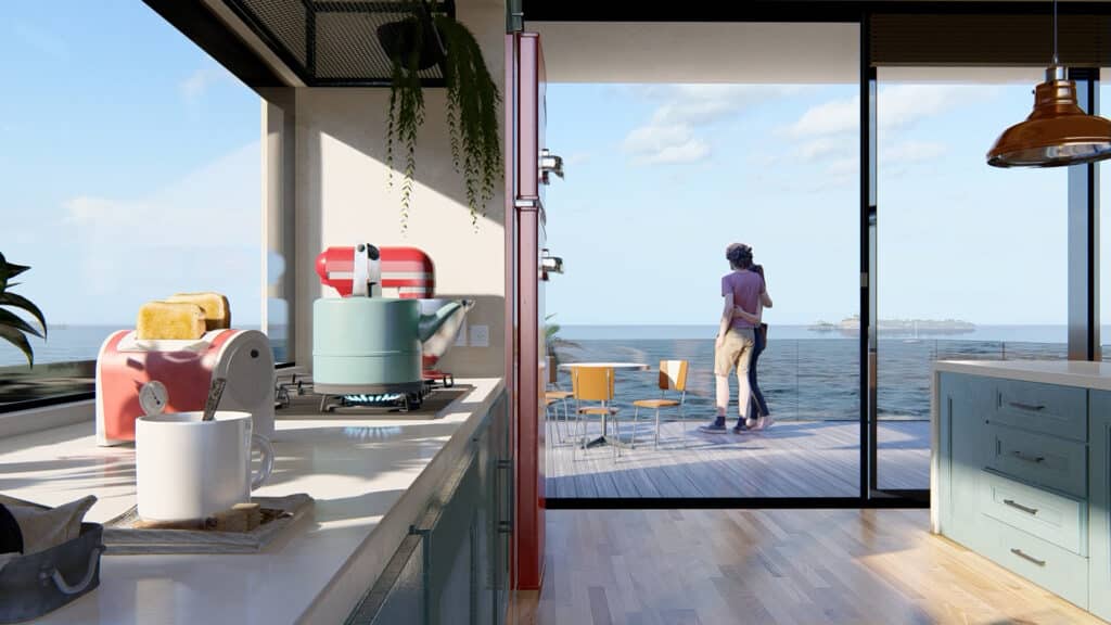
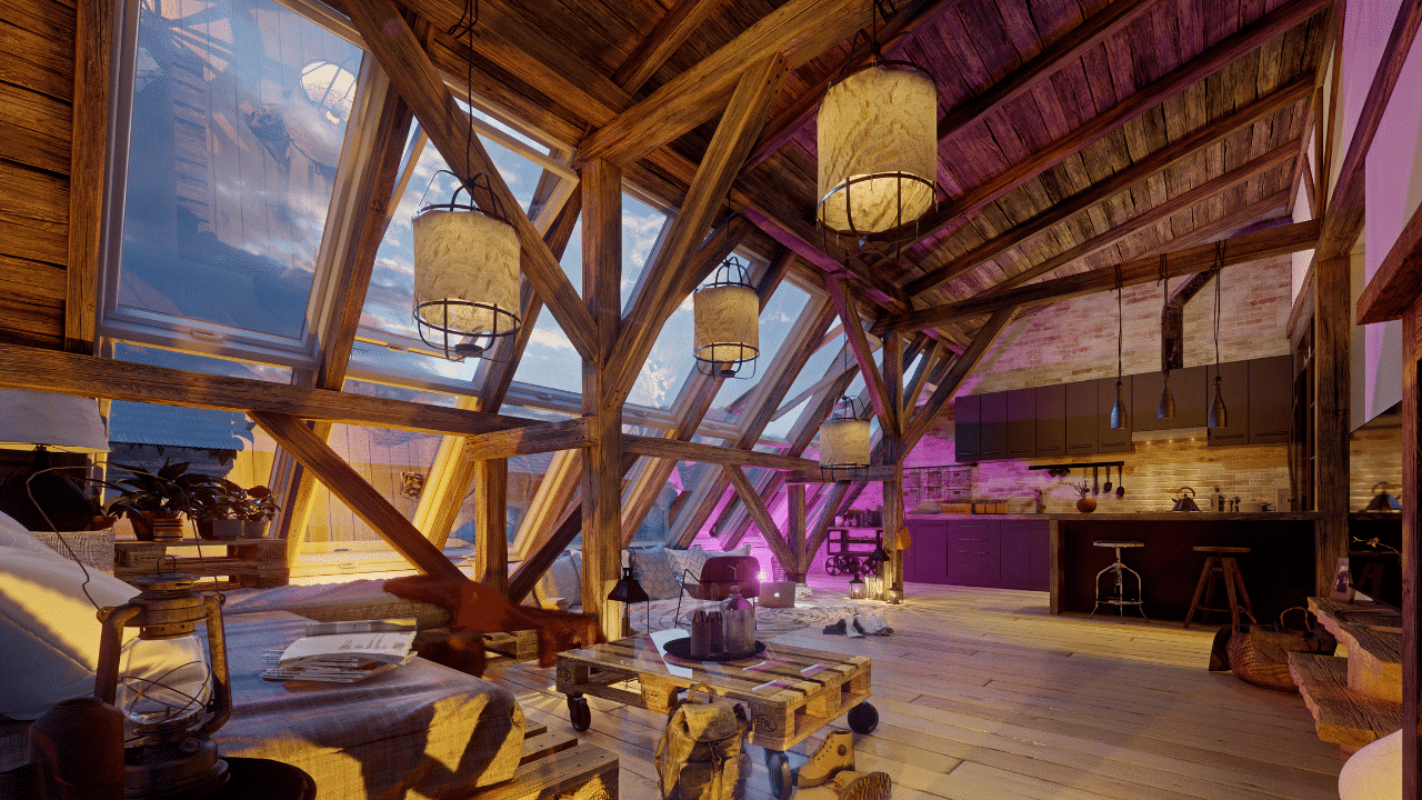
    From the small experiences you share with others to the objects that decorate your home, life is full of feeling. The sofa, coffee table and chairs in the living room, for instance, become a gravitational center where families share peaceful moments together. Papers and pens and books are scattered across a busy home office desk, alongside used coffee cups and photos of loved ones. In the kitchen, the teapot boils and toast pops out of the toaster, signaling the start of a new day.

    These are not just objects, they are reflections of life. They fill spaces with character.

    Lumion helps architects unveil their designs as lived-in spaces, capturing the deeply personal connection between a building, the people who inhabit it, and all the unique objects they bring with them.

    You can render more than a building. Render your client’s dream home, render a story about design that moves emotions, render the space where life happens.

    What’s new in Lumion 11.5

    The latest version of Lumion reinforces its ability to make spaces feel alive with the everyday activities that occur there. You can let your imagination loose and tell a story about a room, a building, or even the entire project, exactly as you see it in your mind’s eye.

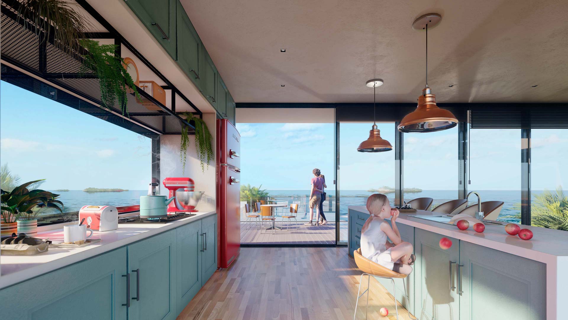
    Lumion 11.5 Pro comes with 123 new objects* in the content library, making it easier to add a human, personal touch to your renders. You can find 73 new retro-inspired objects that reveal the unique identity of spaces, including:

    36 eye-catching kitchen objects, including blenders, refrigerators, toasters, mixers and more.12 furnishings from another era, including café tables and chairs, a jukebox, a popcorn maker and more.
    11 timeless pieces of office furniture, including sofas, desks, chairs, table lamps and more.14 other stylish items, including clocks, radios, a sewing machine, TVs and more.

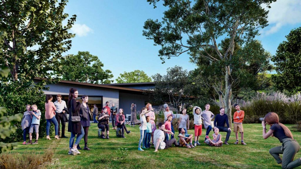
    Additionally, you can express delight throughout your scene with 50 new 3D characters, including a diverse variety of children, teens and adults of different backgrounds and cultures.

    These cheerful non-animated characters are ideal for communicating context, scale and emotion in the background of your project, whether it’s a sunbather relaxing on the grass, a child looking up with wonder, or a couple enjoying a beautiful view together.

    There are infinite stories to tell about your design with the mix of new 3D characters and retro-inspired objects in Lumion 11.5. When combined with Lumion’s existing content library of over 6,300 assets* and over 1,250 materials*, you’ll find yourself on a smoothly paved road to rendering creativity, to bring your designs to life.

    Availability

    Lumion 11.5 is available from June 1st, 2021, as a free update for Lumion 11 and Lumion 11.3 users. Lumion 11 users can download the updated version on your Lumion Account.

    Have more questions?

    Contact us today info@solidcad.ca

    Lumion 11.3 Release Overview

    Architects love using Lumion for one important reason — it breathes life into rendering.

    Lumion makes the process feel like a natural part of your craft, helping you produce beautiful results with ease at every phase of the design project. Its elegantly simple workflow guides you through a rendering experience peppered with moments of unexpected joy.

    Whether for design development or the big client presentation, Lumion 11.3 continues to enhance the rendering process by bringing architects and the art of rendering even closer together.

    No longer will you need hours of frustration and guesswork to produce compelling images and videos of your project.

    With Lumion 11.3, the flow of ideas from your imagination to the computer screen encounters so little friction that rendering becomes an effortless tool in your design toolbox.

    Show the life and emotion in your project, and enjoy the process along the way. Learn more about how Lumion 11.3 changes the relationship between architects and rendering.

    Watch the recording of the webinar by SolidCAD’s product specialists Samuel Plante and Stephane Faulkner and learn all you need to know to get started with Lumion visualization software.

    The webinar covers the overview of Lumion software including some of the new features from the latest release.

    Tip: 5 steps to great renders from Lumion

    This article was originally published on the Lumion Blog.

    You’ve finished your 3D model and imported it into Lumion. Now, it’s time to make it look great. With all of Lumion’s functionality just inviting you to transform your 3D model into a beautiful render, it can be difficult to know where to start. This blog gives you step-by-step hints of what you can do.


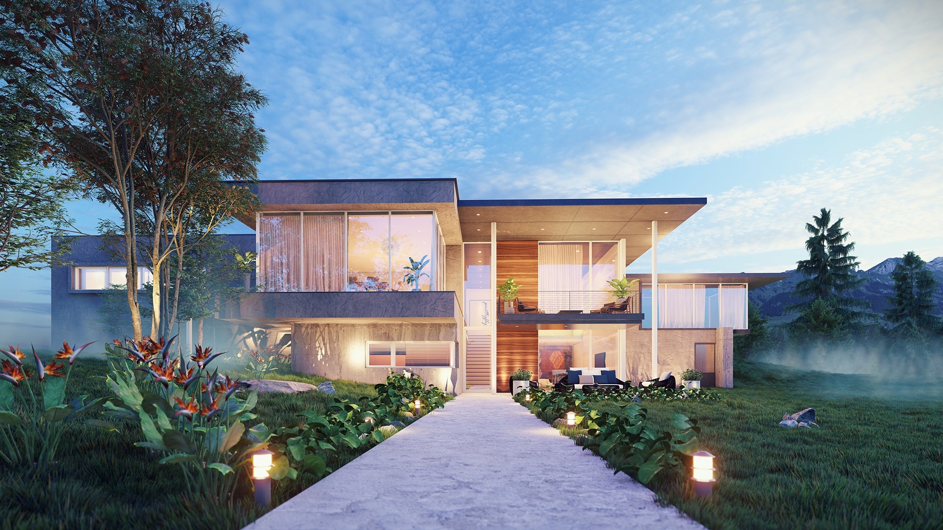
    Villa, rendered in Lumion 9.5 by Gui Felix.


    As intuitive and dependable 3D rendering software, Lumion makes it easy to quickly breathe life into your designs.

    Simply imagine how you want to show your design, and you’ll find a wide range of easy-to-apply tools, features and effects. But before you start building a scene and rendering, there are a few questions you should answer first — 1) how do you want to artistically communicate your model and designs, and 2) how can you make it happen in Lumion?

    Building an artistically compelling image or animation of your designs requires a vision of what you want to achieve. To enhance that vision in your mind, some questions to ask yourself may include:

    1. What emotions do you want to convey?
    2. Are you going for light and colorful, grey and bleak, or something else?
    3. Should the images look realistic or sketchy?
    4. Which parts of the building are you trying to emphasize?

    To help streamline the development of your renders, we’ve provided 5 tried-and-true tips for transforming blank 3D models into beautiful, compelling images and videos.

    Step 1: Find the best point (or points) of view in your scene


    • Use at least one composition rule when framing and finding a camera angle for your image renders. Just a few of these rules include ‘simplify the scene,’ ‘use leading lines,’ ‘be creative with colors,’ and so on.
    • When making an animation, set the camera height to the human eye level. The camera angle shouldn’t be too wide so as to avoid perspective distortion.

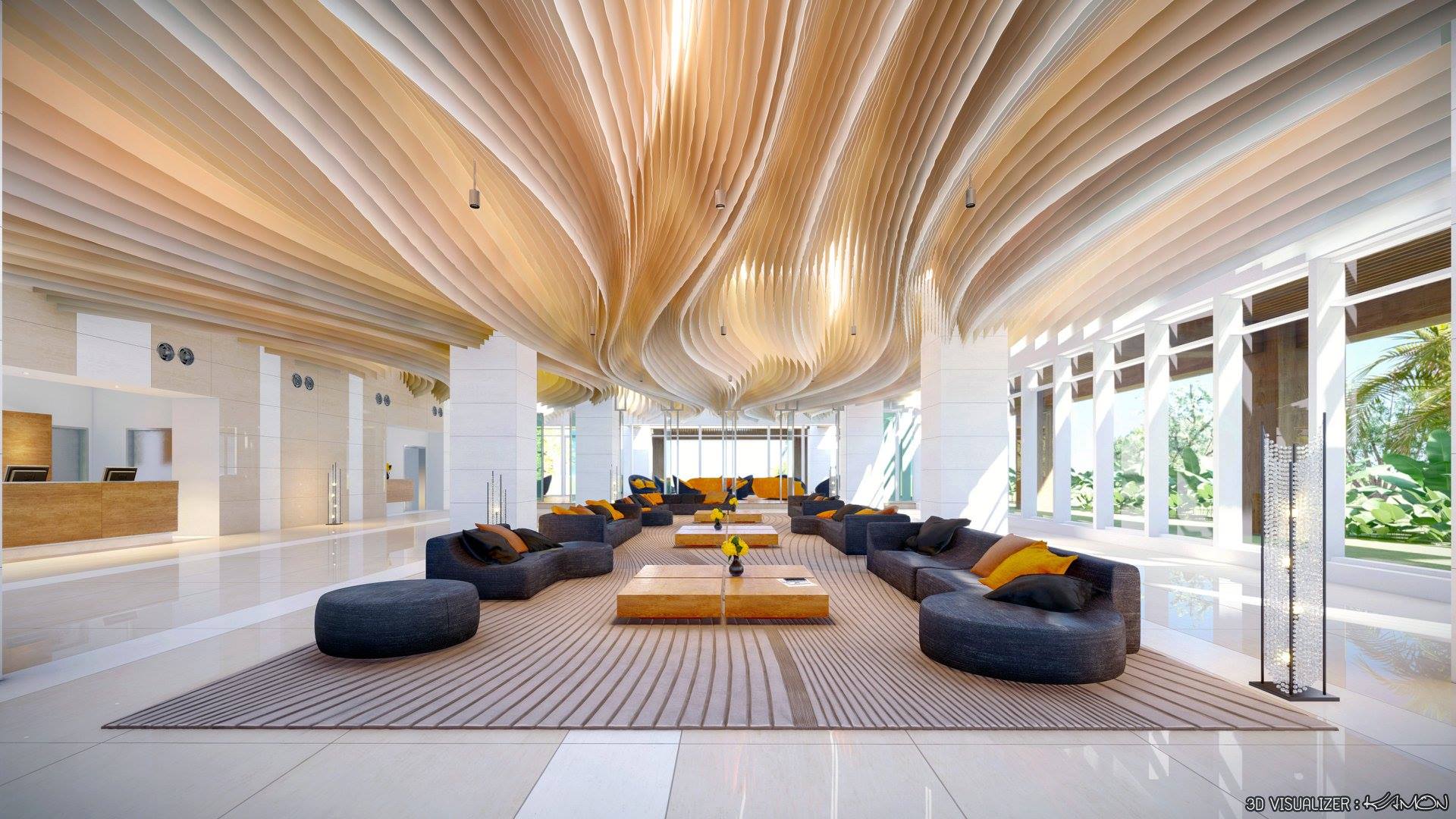
    Interior wave lounge, rendered in Lumion 9 by ‎Kamon Tangruen.

    Step 2: Set up the scene’s lighting


    • Find the best position for the sun so that it draws attention to the parts of the building that you want to highlight. You can use the “Sun Study” effect to accurately simulate the sun location at a particular location, time and date. Other effects such as the “Sun” effect and the “Real Skies” can help you control the environmental lighting in your design.
    • Add interior and mood lighting. Even if the scene you want to show takes place during the daytime, interior and mood lighting can subtly communicate that the building is being used. You can also use volumetric lighting for an extra atmospheric feeling.
    • Balance the shadow brightness and coloring with the context surrounding the building. For example, outdoor shadows tend to show with a bluer color.
    • Avoid a high level of contrast in non-important areas. This is because high-contrast areas can sometimes direct attention to the wrong points in your design.

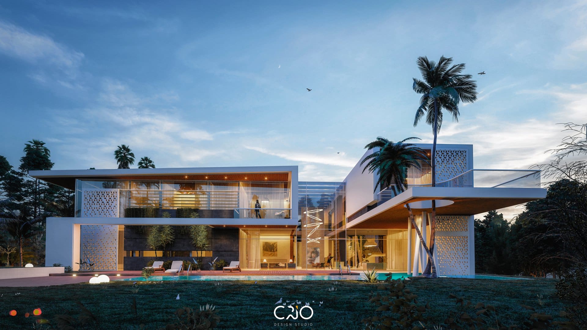
    Villa in UAE, rendered in Lumion 9 by CRIO Design Studio in collaboration with Arch. Alaa Hossari.

    Step 3: Make materials look beautiful with texture and age


    • When rendering, enable “Speedray reflections” and put reflection planes on big, flat surfaces.
    • Tweak the glossiness slider of the floor and ceiling materials. In many cases, making your materials a little more reflective will work better than static, non-reflective surfaces.
    • Do not use simple digital colors, include plain green, red, blue, purple, yellow. These simple digital colors can look ugly when applied to materials. Consider using a more natural (and more realistic) color palette for the entire scene.
    • Sometimes it is better to replace diffuse textures with plain colors (using the top slider in the material editor) and use bumps but without maximal intensity.
    • Consider showing a little age and weathering with the “Weathering” slider, located in Lumion’s material editor.

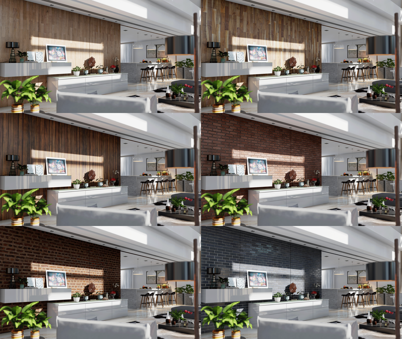
    GIF showing various wall materials, many of which were included in the Lumion 9.5 update.

    Step 4: Adding effects

    • Use the “Color Correction” effect (especially the first slider — Temperature) as it adjusts the color tone of the image and adds dark shadows where necessary.
    • Add a little bit of “Chromatic Aberration” and a very tiny value of the “Fish Eye” effect for a small, optical imperfection.
    • Add “Sky Light” and “Hyperlight” for still images and videos. For the most impact with Sky Light, turn the Sky Light render quality to ultra (which also means “ultra-slow render speeds”).
    • Use the “Sharpness” effect and set the slider to a low value to make the picture look a bit more ‘flat,’ as if were printed on a piece of paper.
    • “Depth-of-Field” (DOF) is really useful for narrow camera angles. Generally, you shouldn’t use this effect if you have wide camera angles.
    • Always add reflections to water and glass planes.

    Step 5: Extra details – every single shot needs them!

    • Furniture is very important for interiors and exteriors. Select and add furniture models from the Lumion object library and fill out some empty spaces. The idea is to make the spaces look “lived-in,” where you show how people might use a building, home, public space, etc.
    • Cars are really effective models when forming the “border areas” of a still render or a movie frame. Try to avoid having cars in the center of your composition.
    • By including people models in your render, you can easily show your audience how you’ve envisioned the relationship between people and a building design. Nevertheless, make sure that your people don’t dominate the render. Their faces should not be too visible so that you don’t distract viewers from the model design. Using silhouettes from the library is a good way to achieve this neutrality with the scene’s people models.
    • You can effectively create picture borders and backgrounds with trees and plants from the content library.
    • Remember that the background of your scene has a huge impact on the look of your building design. Even if the background is blurry, having the feeling of a real city or forest in the background can enhance the realism of the scene while making the entire render easier for the viewer to understand and digest.
    • While the “Real Skies” are beautiful and realistic, they can distract the viewer from the building in some cases. If you feel that the skies are distracting, you have a couple options. For one, you can use one of the “clear” Real Skies or you can add the Sky and Clouds effect and turn up the “cloud softness” slider to blur the clouds. Another option is to turn off any cloud effect and adjust the “clouds” slider in Lumion’s Build Mode to create a distraction-free, clear sky. Below, you can find a picture showing the difference between “no clouds” in Lumion and the clear Real Skies.

    Making more beautiful, realistic, and detailed renders in Revit

    3D visualization is an essential part of architectural illustration today. Renders allow you to communicate your vision and intent to clients and colleagues. This is why models or drawings are often sent out to be professionally rendered. This is an expensive but usually necessary process. However, it is possible to make high quality renders in-house using Revit or through the cloud.

    What makes a beautiful render? Like many things, beauty is in the eye of the beholder. It is in the nuance of the materials you select, the lighting, the details you choose to include, and any post-production editing.

    Here are a few thoughts on how to start making more beautiful, detailed renders in Revit.

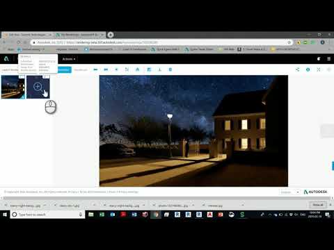
    I’ve wrapped them all up in a short video at the bottom of this post.

    Materials

    Materials are the foundation of every Revit render. They are what gives an element in Revit its color, context, and texture. They are part of the scene and should be adjusted accordingly.

    The default color in Revit is grey. Leave the materials on their default setting and when you hit the render button, you will get a series of grey blobs with no information or appeal.

    Luckily you can easily change this by adding texture to the material. Look in Revit’s image library or Google JPEG’s or PNG’s with your desired texture. Remember that you can also experiment with attributes like reflectivity and transparency to get the textures looking just right.

    Details

    It is the details that make a render feel realistic. Buildings do not sit in a vacuum. Neither should renders. The more detail you are able to add to your render, the more more realism there is to your images especially when you work with real-life details. Beautiful renders are photo-realistic. As in photos – trees, people, and other outdoor elements – create the scale and real-life feel. Real pictures are never perfect and a hundred percent clean so neither should your render be.

    Sun and Artificial Light

    Light is the most important aspects of a rendered image. The lighting of your building should match the lighting of your surrounding. Everything should look like it works and is meant to be together. The shadows should look good and the lux, luminous or wattage should be correct on the artificial lights you are using.

    Although you can adjust the exposure afterward rendering you don’t want to be spending all your time doing adjustments. Try to set up the image correctly from the very beginning. This becomes even more important if cloud credits are involved.

    Tip: It’s a good idea when trying to render your design to have lights hidden away from the building. This will add some hidden light in the hidden corner or in the back of the camera to give some illumination to the building, just make sure to delete them where they are not needed.

    Editing the Render

    You can adjust the render after you have rendered it. This is a good way to make minor changes without having to render all over again. You can make things darker or lighter. Change the color make it warmer or cooler. It is sometimes essential to work on some area of the scene to add some dramatic shadow or to correct some texture. You can do this within Revit without having to export to another software like Photoshop and it will hopefully save you time and money..

    Walk through the rendering process with me.

    Revit Family Guide – Master Revit Families in 10 Steps

    A Family is a group of objects that form a building component such as a door, a wall, a window or a chair. All families are associated to a specific category and contain a set of properties (parameters) and a graphical representation associated to these properties.

    Understanding how to create and edit Revit Families is a must if you want to take your Revit skills to another level. Revit’s Family Editor has all the tools you need to create custom components for your Revit projects, and here you will learn 10 steps to master this environment.

    #1 – Understand family types

    There are different Family Types in Revit:

    System families – Generally, assemblies (walls, roofs, floors, ceilings, etc). Our flexibility here is limited, we can create different types of system families, but we can’t add parameters to control their graphical representation.

    Component families – Families we can create from scratch and load into the project. Can be extremely flexible and customized based on your needs. In this blog post, we are going to focus on them. They can be hosted, free standing or work plane-based.

    In place families – ‘One-off’ families created inside the project environment that do not require geometrical flexibilization. Should be used with caution, as they can increase the size of the file and impact model performance.

    #2 – Understand the use of parameters

    Parameters are used to define and modify elements in Revit. They give flexibility to project components. By changing the parameters assigned to a family we can create different versions of the family, called types. Each family type has an identical set of parameters called “type parameters”.

    When placing a family type in a project, you create an instance of that element. Each instance has a unique set of parameters called “instance parameters”. By changing these parameters, you can apply changes independent of the family type, that will only apply to that specific element in the project. Keep in mind that if you make any changes to the family type parameters, the changes apply to all element instances that you created based on that type.

    It is up to the person creating the family to define its parameters, and to determine if a parameter is going to be applied to the type or to the instance level. The following pictures are a good example of that statement. These two doors are very similar graphically, but each one has different instance and type parameters – for example, one door has a parameter called “Door Material” and the other “Panel Material” with, essentially, the same function. Why? Probably just because they were created by two different Revit users.

    #3 – Plan before you start

    Planning is a key process to successfully create a family in Revit. Sketch you family in a piece of paper, to make sure you don’t get carried away in the process. It is common for new Revit users to feel that they should “model everything” in full 3d, but following this road usually leads to over modelled elements that are hard to use and manage.

    Answer the following questions before you go to the next step:

    #1 Is there a family in Autodesk’s library that is similar to the one you want to create? Consider copying, renaming and modifying the existing family to save time.

    #2 Where will the family be viewed? Is it only showing in plan? Is a 3D representation required? Will it be rendered? Can we get away with 2D lines? Only model in 3D what is necessary.

    #3 How do you want it to graphically show in different views? What is the level of detail you need based on the scales of the drawings in which it will be represented? Consider setting visibility controls.

    #4 What is the level of flexibility you need? What properties do you want to be able to control? What parameters must be created? Is a property dependent on another? Consider creating formulas to create relationships between parameters.

    #5 Will the family be scheduled? Is a parameter going to be scheduled? Consider using shared parameters.

    #4 – Select an appropriate template

    Revit comes with a variety of templates based on object categories. Go to File > New > Family and select an appropriate Template for your family. Categories will determine the behaviour of the family – for example if the family goes from level to level, or if it is hosted in another element. If you are not sure what category the object falls under, then create it as a generic family and you can modify the category later going to Create > Properties Panel > Family Categories and Parameters. Be aware that object categories are what control the display of objects in Revit and several categories are “non-cuttable” in Revit.

    #5 – Create the family framework

    Most templates come with, at least, two pre-defined planes. The intersection of these two planes defines the origin of the family. If you want your family to be able to change in size, you need to build a framework using reference planes and/or reference lines (used to constrain angles).

    Use reference planes to set critical positions in the family. Later, we will constraint the geometry of the family to these reference planes so when they move, the geometry follows.

    The picture below shows the reference planes you would create if you wanted to create a table – reference planes in plan view for the table top, and reference planes in an elevation to set the top and underside of the table top.

    #6 – Dimension the framework

    Go to Modify > Measure Panel, select a dimension tool and dimension your framework. Then, create constraints defining both flexible and static conditions.

    Select and lock a dimension.

    Select and set a group of dimensions as equal with the “EQ” option.

    Label a dimension with a parameter to be able to control its value dynamically. Select a dimension, go to Label Dimension Panel and click Create Parameter. Give the parameter a name, a group and define if the parameter will be applied to type or instance (you can change this later). Notice that if you select a dimension, the dialogue defaults the parameter type to dimension, and length.

    In our example, the table top length, width and thickness are flexible and labeled with parameters. Equality constraints have also been included so when Length and Width change, the center remains in the same position. The Height of the table, on the other hand, is fix and locked as 970 mm. No parameter was created, because there was no need to make it flexible.

    After setting your parameters, you can edit them inside Modify > Properties panel > Family Types.

    The blue heading bars in the picture above are the groups under which you can create each parameter. Make sure you group your parameters in a logical and ordered manner (you can move parameters up or down and edit their groups if you need).

    The name of a parameter is also very important. Use short but descriptive names and don’t use ‘-‘ signs because Revit may confuse them as formula values. Also keep consistency for naming conventions – will they have first letter cap, all caps or all lower case?

    Notice that parameters can also be driven by formulas. In the example below, the Width was set to be half the Length. It is also possible to insert conditional statements. Conditional statements can contain numeric values, numeric parameter names, and Yes/No parameters.

    Before going to the next step, test your parameters and see if the reference planes are moving the way you expected. Insert new values and hit Apply. Use values outside the anticipated range. If your framework has a glitch, now is the time to fix it.

    #7 – Model and constrain the geometry

    After creating the framework and the constraints, and making sure they are going according to plan, it is time to add the geometry. Go to Create > Forms Panel and select an appropriate massing tool – Extrusion, Blend, Revolve, Sweep, Void.

    Draw the geometry and constrain its edges to the reference planes using the align tool. Finish the sketch and align/lock the geometry in other views if applicable.

    Once you have locked the geometry to all applicable reference planes, it’s time to run additional tests to see if the family is working properly.

    Avoid creating addition dimensions and reference planes inside the Sketch Mode. They will not be visible once you leave the sketch and will make it hard for you to manage the family in the future. Additionally, avoid constraining modelled elements together – always prefer to constrain modelled elements with reference planes instead. This will reduce the risk of having family crashes and corruption down the road.

    Repeat the process to include all the geometry you need in the family – create a framework, constrain the framework, add geometry, constrain geometry to the framework, test it. Keep in mind that creating a family in a slow-paced manner, running constant tests, is the best way to succeed. If something goes wrong in your parametrization, you might have a hard time to find and fix the problem if you implemented several untested changes all at once.

    #8 – Improve your family

    Improve your family by creating additional geometry, parameters and relationships.

    Add shared parameters for information you need to schedule or tag in your project.

    Set materials to your geometry. If the material of an element will always be the same, select the element, go to Material field and hit the “…” to select a material. If the element may have different finishes, create and apply a parameter by clicking on the box on the right side of the Material field (marked in yellow in the picture below).

    Set visibility yes/no parameters to elements if you want to be able to control if they are visible or not. To do that, select the element and define a parameter by clicking on the box on the right side of the Visible

    Use nested families to make changes more efficient and shift from one family type to another using a “Family Type” parameter – see how leg types are controlled in the example below.

    #9 – Add visibility controls

    By selecting each element and setting a Visibility Setting, you are able to control the level of detail and the view types in which your elements will be visible. This can be useful, for example, if you want to use simplified 2D lines to represent a family in plan and elevation but wants to see all modelled components of that family in a 3D view.

    For greater control and flexibility, Revit allows you to create subcategories of the any category in the family editor. Go to Manage > Object Styles and create a new subcategory. Then, select the element and apply it using the Properties Window.

    #10 – Create Family Types

    Before you load your family into a project, go to Modify > Properties Panel > Family Types and create default types. Use descriptive names that reflect the type parameters that are part of the family.

    Now it is your turn

    In this blog post we covered the main concepts and tools for you to create powerful and flexible families for your Revit projects. Now it is up to you to create your first family. Start with a simple family and go through all the steps listed above.

    Creating Revit families can be intimidating at first but, once you understand the concepts and get used to the process, you will be able to explore endless design possibilities without depending on 3rd parties’ content.