Introduction
Navigating through the intricate world of Dynamo, it is crucial to stay updated on its continuous enhancements and refinements. In this part, the first of a series dedicated to Dynamo updates, we’ll delve into six (6) user-centric new features and enhancements aimed at enriching the user experience and broadening the horizon of what is possible with visual programming.
This blog aims to nurture curiosity about Dynamo, encouraging the reader to explore its capabilities and experience with its features.
In this part 1, we will discuss the Six (6) New features and enhancements.
- Enhanced Node Autocomplete
- New Dynamo settings with Import/Export and Deployment
- In-Product Node Documentation
- Insert Graph into an Open Workspace
- Enhanced 3D Node Preview in Dynamo
- Improving Workspace Organization with Advanced Grouping
Each of these enhancements is designed to cater to different aspects of the Dynamo experience, whether you are an architect, engineer, designer or a passionate Dynamo enthusiast, these improvements have the potential to elevate productivity and deliver more efficient BIM projects, saving valuable time.
Enhanced Note Autocomplete – Smart Recommended Nodes
Feature Overview
The world of visual programming is continually evolving, equipping developers with more refined tools and functionalities. Among the recent enhancements in Dynamo is the “Recommended Nodes” feature in Node Autocomplete.
Dynamo’s Node Autocomplete, once enabled, now features a “Recommended Nodes” enhancement driven by machine learning. This improvement provides more relevant node suggestions based on Confidence Level. Suggestions are derived from extensive training on real-word Dynamo patterns. Users have the flexibility with Low Confidence suggestions can easily switch suggestions methods.
A Deeper Dive
- Introducing the “Recommended Nodes” Feature in Node Autocomplete
Dynamo’s Node Autocomplete has been enhanced with a significant feature: the “Recommended Nodes”. This feature, driven by advanced machine learning, it offers precise node suggestions to optimize the visual programming workflow.
- What is “Confidence Level” for Precision in Suggestions?
Once the Node Autocomplete is enabled in the Preferences, it can be activated by double-clicking on an Upstream or Downstream node port in the graph. the Autocomplete node ranks suggestions to ensure the most relevant and appropriate connections are prioritised. Each suggested node is assigned a Confidence Level, reflecting the algorithm’s certainty about its relevance and suitability within the given context. A higher confidence rating (percentage) prioritises nodes that are more pertinent, further prioritising the design process.
- What are node rankings and suggestions from Real-World Learning?
The node rankings and suggestions are derived from the algorithm’s extensive training on the Dynamo dictionary, Dynamo host samples, and real Dynamo graphs. By understanding real-world patterns, it can make informed recommendations. As a result, the Autocomplete node offers customised and reliable suggestions, that can significantly improve the visual programming experience in Dynamo.
- What is “Low Confidence” nodes?
Nodes assigned a lower ranking percentage are considered nodes that the algorithm have less confidence in their usability/match with the selected port and are conveniently categorized under “Low Confidence”. They are available for optional selection, ensuring flexibility in node choices. The criteria for which nodes fall under “Low Confidence” can be adjusted.
- How to swiftly alternate between the Ranking Methods?
Regardless of the Preferences settings, users can effortlessly switch between the Recommended Nodes and the previously existing Node Type Match method directly from within the Autocomplete node. This ensures a seamless workflow, eliminating the need to delve into separate settings or menus.
Enabling Node Autocomplete – Step-by-Step
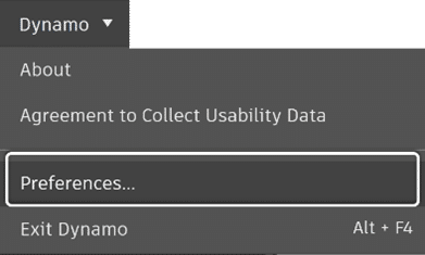
- From the Dynamo tab, select Preferences.
- Under Features, locate the Node Autocomplete option and expand it.
- Toggle the switch to ‘On‘ to the left of Enable Node Autocomplete.
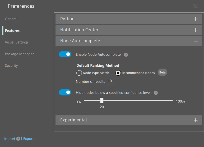
- Select the Default Ranking Method
- Type the number of nodes that will show in the Autocomplete node
- Toggle the switch for Hide nodes below a specified confidence level to ‘On‘
- Close the Preferences Panel
How to Select nodes from the high-ranking List – Video
Beginning with a single node:
- Autocomplete node is initiated by double clicking on one of the node’s input ports
- Top ranked node is selected from the list
- This process is repeated for the other ports
How to Select nodes from Low Confidence list – Video
Beginning with a single node:
- Autocomplete node is initiated by double clicking on the Category input port of the All Elements of Category node.
- The top ranked Category.ByName node is selected from the list and automatically connected
- Autocomplete node is initiated by double clicking on the Name port of the Category.ByName
- The String node is selected from the Low Confidence list and automatically connected
Feature summary
The introduction of the “Recommended Nodes” feature, enhances the functionality of Dynamo’s Node Autocomplete. Utilising machine learning and data from real-world usage patterns, this user-centric enhancement allows users to create graphs with greater efficiency. With the added flexibility to feature aims to provide ore relevant and reliable node suggestions. Alongside the ability to adjust confidence criteria and switch suggestion methods, users have tools at their disposal to refine their visual programming experience.
- New Dynamo setting with import/export and deployment.
Feature Overview
In the vast spectrum of visual programming tools provided by Dynamo, the ability of exporting and importing settings using XML files stands as another practical addition, accessible right from the Preferences panel. This feature not only facilitates the sharing, deployment, and transfer of preferences, but also serves as an efficient backup mechanism. Ensuring consistency in Dynamo settings across the company, it provides a safeguard against unintended changes and streamlines collaboration efforts.
Exporting Settings in Dynamo from the Preferences Panel – Step-by-Step
Note: Before making changes or importing existing preferences, exporting current configurations to an XML file is a prudent step. This acts as a backup, allowing importing them back if needed.
- From the Dynamo tab, select Preferences.
- In the “Preferences” dialog box, click on the section (that contains the specific settings to export.
- Expand Subsections: Expand subsections to reveal the individual preferences.
- Review and Set Preferences: Review the individual preferences and ensure they are set according to your desired configurations.
- Export Settings: Once you have reviewed and set all the preferences you want to export, click on “Export” within the “Preferences” panel to initiate the export process.
- Choose Export Location: A file explorer window will appear, allowing you to choose a location for saving the exported settings file.
- Rename File: The first exported settings file to that location, will be automatically named “DynamoSettings.XML”, otherwise the file of the being exported will have a suffix appended to it (i.e. DynamoSettings_12345678.XML). Renaming the exported file or adding/replacing the suffix will help identify the settings later.
- Close File Explorer Window: After providing the file name and selecting the export location, close the file explorer window.
The exported XML file will contain the chosen configurations and can be used later to import the settings into Dynamo or share them with others who might benefit from the same configurations.
Importing Preferences – Step-by-Step
Weather reapplying exported settings, deploying them across multiple instances or incorporating received ones from another user, the effort is minimal. Simply use the Import tool in the Preferences panel to integrate them.
- From the Dynamo tab, select Preferences.
- In the “Preferences” dialog box, click on Import
- Locate the XML file: Locate and select the XML file that contain the configurations you want to apply and select it
- Import Success? Click OK
With these few steps, the settings in the Preferences panel will update to reflect the ones imported thru the chosen XML file.
For settings outside the Preferences panel in Dynamo, it is necessary to restart both Dynamo and its host program for the settings to take effect.
Deployment with XML files
Using XML files for transferring preferences, offers a structured method for sharing, transferring, or reverting settings in Dynamo. It supports uniformity, collaboration, and quick settings adjustments.
How to Export and Import Settings – Videos
Here are two short videos that demonstrate how to export and import setting using XML files:
- The Node Autocomplete feature is enabled, and the Auto-Backup Interval time is modified
- The preferences settings are exported to an XML file that is renamed
The preferences settings are exported to an XML file that is renamed
- An existing XML Dynamo settings file is imported in which the Node Autocomplete feature was disabled, and the Auto-Backup Interval was set to 1 minute
Feature Summary
Utilizing XML files, Dynamo’s export and import tools offer a straightforward approach to managing configurations, remaining a user-centric environment by enabling users to both preserve and modify their setup.
In-Product Node Documentation
Feature Overview
Dynamo’s revamped Documentation Browser simplifies node understanding with improved in-product node documentation. The Documentation Browser Accessed by right clicking a node and selecting Help…, it organizes information into three main parts: Node Information, Inputs and Outputs and Node Issue Help when things don’t go as planned.
A feature familiar to many, the Documentation Browser is Dynamo’s in-product node documentation designed to give users quick access to node details without leaving the application. It is now reimagined and refined to provide more organized and detailed per-node documentation.
Feature Details
The Documentation Browser is now segmented in 3 sections:
- Node Information: This section provides information about the selected node. While the aim is to offer clarity on a node’s functionality, some nodes have In Depth information.
- Input and Outputs: This section presents a breakdown of the nodes inputs and outputs complete with their type, a brief description, Inputs Default Value and Outputs Data type.
- Node Issue Help: This section appears only when a node error is detected. It is intended to offer guidance to address the error.
The enhanced in-product node documentation provides structure and efficient way for users to access and understand vital information. This streamlined approach addresses the fundamental need for clarity and accessibility in Dynamo’s complex environment.
In-Product Node Documentation – How it Works – Video
Showcasing the improved in-product node documentation within Dynamo offers just a glimpse. It is recommended to dive into the improved documentation firsthand, allowing for a richer understanding of its advancements and nuances.
Insert Graph into an Open Workspace
Feature Overview
Dynamo’s “Insert” tool, amplifies the modular assembly approach in visual programming., by streamlining the integration of graphs within graphs or within empty workspace. This enhancement ensures a boost in workflows efficiency, reusability, modularity, and clarity within the Dynamo ecosystem.
The optimization of the user experience in Dynamo is enhanced by the “insert” tool. While copy-pasting graphs served as a functional method, this new tool provides an elegant, integrated, and straightforward approach for optimizing the workflow even further.
Feature Benefits
- Precision: Minimize manual errors and ensure that graphs are integrated correctly
- Efficiency: Speed up the process by bypassing the older copy-paste approach.
- Streamlined workflow: This tool’s introduction fits seamlessly with established workflows, simplifying the integration/nesting process.
- Enhanced Collaboration: Ensures that graphs to be nested maintain their functionality and integrity when shared among different users
Workflow enhancements
This functionality goes beyond nesting graphs, it reshapes how professionals approach their graphs creation in Dynamo. While enabling efficient integration, it offers:
- Modular approach: Emphasizes the discrete unit of design, promoting a design as you go approach and encouraging decomposing complex tasks into distinct graphs and seamlessly stitch them together in one file as needed.
- Reuse & Recycle: Once a graph is created, it can be reused repeatedly across different multiple projects, maximizing efficiency.
- Maintained Clarity: It promotes preserving a tidy and organized library that is ready for integration.
Inserting a Graph into an Open Workspace – Step-by-Step
The introduction of the “Insert” graph tool in Dynamo, elevates the visual programming experience of both novices and seasoned users, fostering better organization and collaboration leading to an increased efficiency.
- Start a new graph or open an existing one in the workspace.
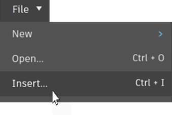
- Navigate to the File tab and select Insert.
- Locate the graph you want to insert and select it. (Note: If the graph is inserted in an existing graph, it will be located below it)
- Review and connect the newly added graph as desired.
Feature Demonstration – Video
Like other tools in this version, this tool has also to be experienced firsthand.
In this demonstration 2 graphs will be inserted in a new file, and stich together to export door’s data from a Revit project to an Excel file.
Enhanced 3D Node Preview in Dynamo
Feature Overview
Dynamo’s 3D Watch node ensures the geometry remains in sight, even when the connected node preview is turned off. This feature provides an uninterrupted spatial understanding without distractions
In certain cases, there may be no need to toggle node preview of a node on just to see the spatial context. Watch 3D now shows geometry for all directly connected nodes, even if their preview is turned off. With this update designers can remain immersed in their workflows while still retaining visual clarity.
How it Works – Step-by-Step
- Right click the node connected to the 3D Watch node and uncheck Geometry Preview.
- Run the graph. The geometry will stay visible in the 3D Watch Node after the graph.
This enhancement is not merely a technical update; it is a thoughtful design decision. It acknowledges the core principle that visual continuity is a must in spatial design tools like Dynamo.
How it Works – Video
In this demonstration the Geometry Preview is turned off in the GeometryColor.ByGeometryColor node. After the graph is run, the color disappears in the background but remains in the 3D Watch node.
Improving Workspace Organisation with Advanced Grouping
Feature Overview
Another enhancement in Dynamo is group functionalities. Custom Group styles, resizable headers, intuitive color adjustments, various customization option, together with the added convenience of dragging nodes into groups and, removing them using Alt+Left Click, makes organising the workspace a more intuitive endeavor. Additionally with settings exportable from within the Preferences panel, sharing. Backup, or deployment becomes smoother and more consistent.
Feature Details
- Resizable Headers: Customize to content’s needs. Adjust the headers size for better readability or a neater visual look.
- Automatic Text Color Adjustment: Dynamo toggles between black and white text based on group’s background color, ensuring readability.
- Direct Access, Drag & Drop and Easy Removal:
- Quick Style Change: While Styles are created and set in the Preferences panel, Adjustments like color and font size are just a click away with the context menu.
- Direct Node Organisation: Dragging a node straight into a group for swift organisation.
- Easy Node Removal: Removing a node from a group is made easy using Alt+Left Click.
- Exporting Settings Via Preferences: Groups Styles Settings can be backed up, shared and deployed by using the Export tool in the preferences panel. Consistency is ensured across teams and projects.
Why it Matters
The enhanced grouping functionality in Dynamo emphasize:
Efficiency: With intuitive nodes organisation, direct style customization and easily readable group labels, workflows become faster and smoother.
Collaboration: he ability to export and share settings ensures that teams work with a consistent visual framework, enhancing collaborative effort
Personalization: With a wide range of customisation options, Dynamo allows users to create a workspace that reflects their styles and project needs.
Dynamo’s advanced grouping features in this update increase clarity and efficiency, adapting as workflows grow in complexity. The result is potentially a better organised, efficient, and customized visual programming environment.
How it Works – Video
In this demonstration, a new Group Style is created and applied to a group and text size is changed.
Part 1 Conclusion
The six Dynamo enhancements we explored in this blog are clearly geared towards refining the user experience a boosting efficiency in visual programming. From Node Autocomplete to the revamped group functionalities, each feature aims to empower design professionals even further.
Keep an eye for the part II of this Dynamo for Revit 2.17 series where we’ll keep spotlighting more of Dynamo’s updates throughout. Until next time!
For any questions reach out to your sales rep or contact us at info@solidcad.ca