• WHAT’S NEW IN REVIT ARCHITECTURE 2024.1

    BY: Mahsan Omid

    The latest version of Autodesk Revit (2024.1) is just out!

    Soon after the last release of version 2024 in April this year, Revit 24.1 continues to promote some of the most intriguing and much awaited enhancements. This release includes features and enhancements for data management, visualization capabilities, more accurate documentation, design efficiency and reduce re-work. Let’s take a look:

    Search and zoom in the project browser.


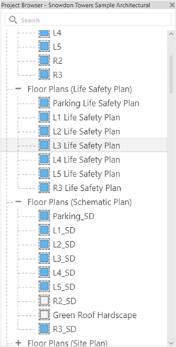
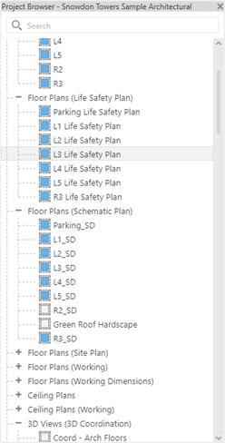
    The latest update introduces improved zoom functionality in the Project Browser by utilizing the CTRL key + mouse scroll. This allows users to easily zoom in and out, providing a seamless and consistent zooming experience throughout the application.


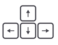
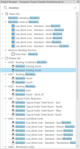
    2- Up/Down navigation after searching in Project Browser

    Explore Project Browser search results using the Up and Down arrow keys. Get faster to a selected search result.

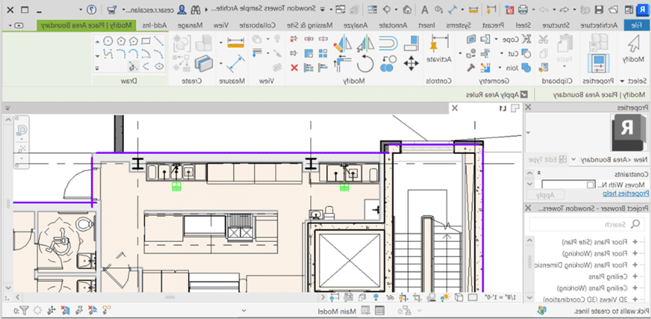
    3- Apply Area Rules setting

    In Revit 2024.1, Revit now remembers the “Apply Area Rules” settings shows up in options bar when creating or modifying Area Boundaries. The remembered values is stored in the Revit.ini files, under the ‘AreaBoundary_ApplyAreaRule’ variable.

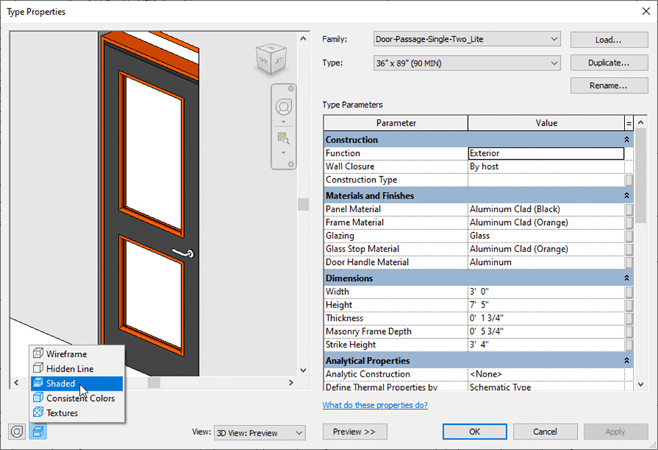
    4- Add visual style in type preview

    To better visualize how an element is displayed in your model, apply a visual style to the element in the Type Properties dialog.

    Use the control in the lower left corner of the preview pane of the Type Properties dialog to change the visual style of the preview.

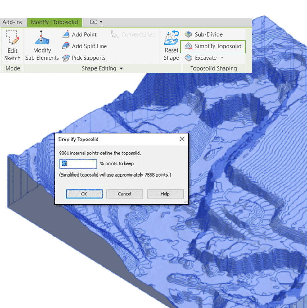
    5- Site Design- Simplify Toposolid

    You can adjust the number of internal points in a Toposolid by inputting the percentage of points to preserve.

    Input number ranges between 0-100% Revit will provide instant point number changes responding to the input text. Input 0% will remove all the internal points, but please note the points on boundary will be preserved and remain untouched during the simplify process.

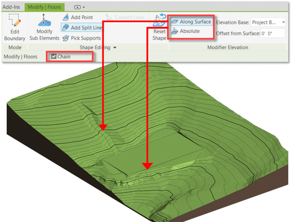
    6- Site Design- Add Split Line enhancement and Chain Line Selection

    Now users can have consistent behavior between Add Point and Add Split Line

    Split Line Enhancements

    You can create Chain lines Along the surface with the same offset to create Path along the existing Topo. ​You can create Chain lines with Absolute height to easily shape the Topo to a flatten area.

    Chain Selection on Split Line

    In the previous version of Revit, you were limited on selecting the uppermost split line in a triangulation facet, or select a triangulation facets. ​

    In Revit 2024.1, you can Chain select any split lines. The splines do not need to form a closed loop. You can also modify the elevation of a chain line selection at once.

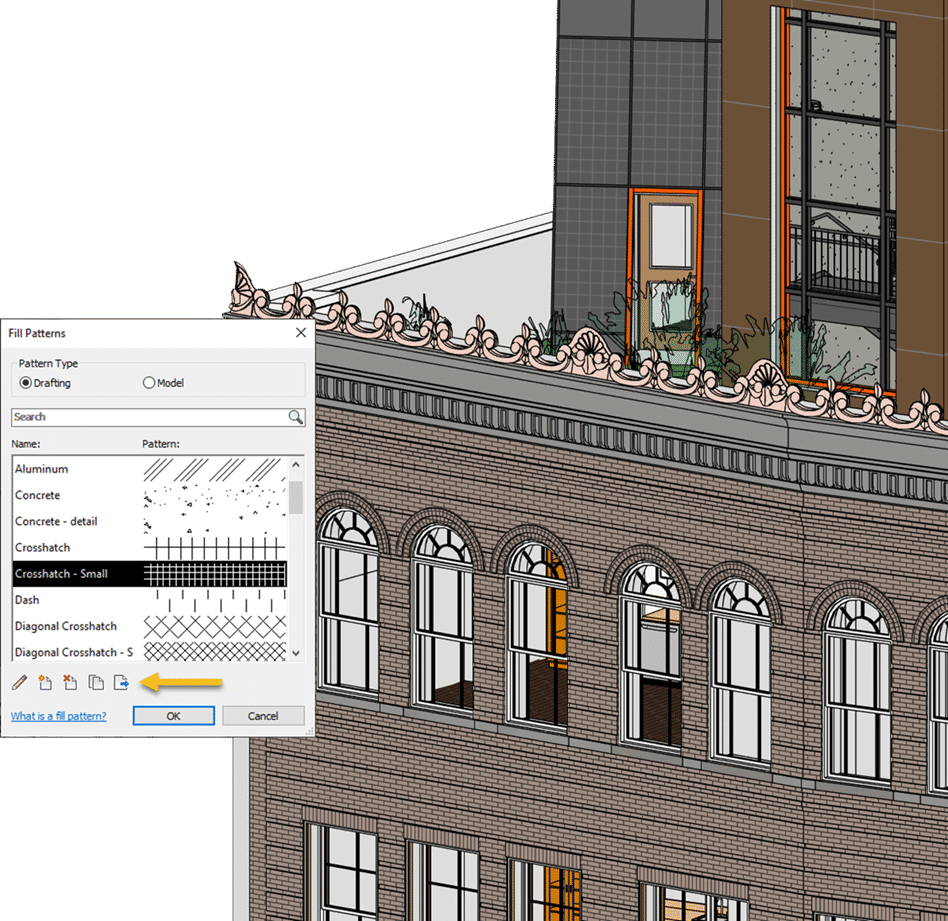
    7- Export Patterns to a .pat file

    In Revit 2024.1 you can export drafting and model patterns from your model to a PAT file.

    In the Fill Patterns dialog, accessed from the Manage tab, select a pattern or multiple patterns to export to a PAT file. The exported file contains pattern definitions of each pattern selected. Drafting patterns and model patterns must be exported to separate PAT files.

    8- Performance improvement on placing

    Provided a fix to reported lag when placing, pasting, and moving floor-based families and room, area and space tags

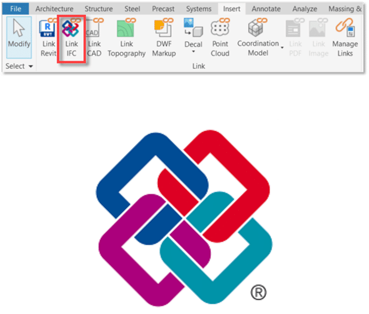
    9- Enhance Link IFC fidelity

    Autodesk is using ATF (Autodesk Translation Framework)  to better support the resolution of external geometry for large IFC models, and accurately represent geometry edited with Boolean operations.

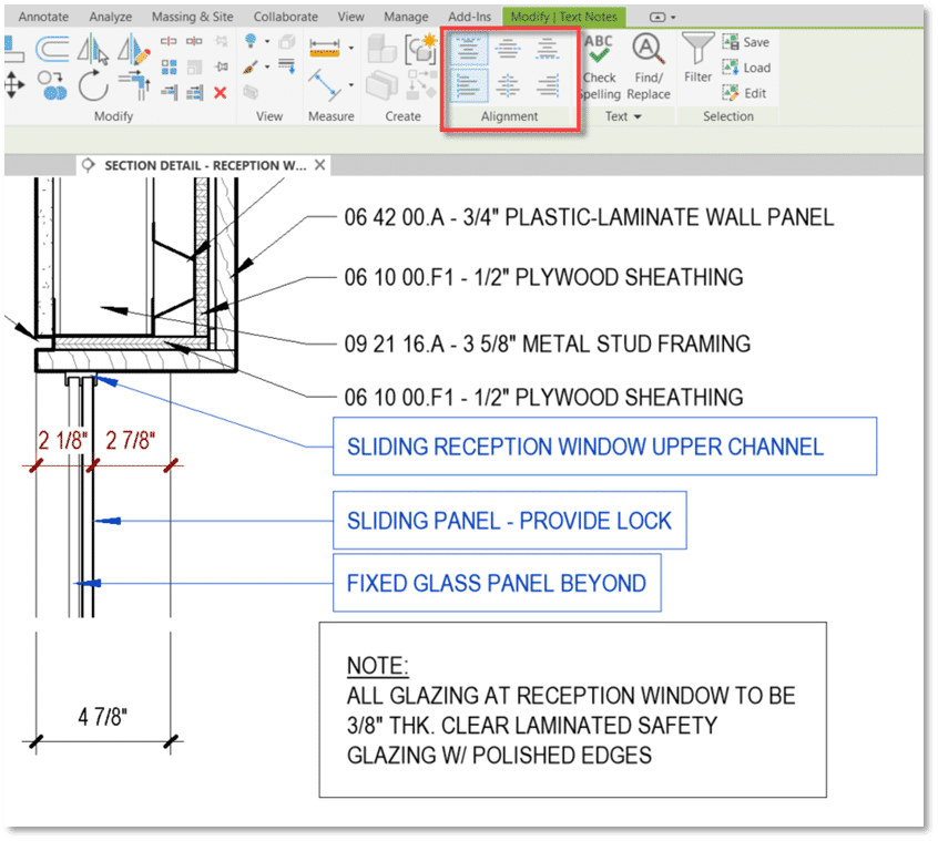
    10- Change text alignment property for multiple selected elements using the ribbon

    This improvement allows users to the control text alignment property for multiple selected text elements – this could be done previously in the properties palette, but that was difficult for users to discover and had difficult drop downs without icons.​

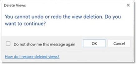
    11- Warning for Delete Views in workshared models

    Deleting views in a workshared environment cannot be undone.

    To prevent any accidental loss of data, Revit now displays a warning for deleting views from the Project Browser. The warning message can be optionally disabled.

    If you want to learn more about Revit feel free to Contact us 

    Flow and Pressure Drop Calculations Available in MEP Fabrication Elements

    Have you noticed in Revit you have to choose between ducting and piping that supports flow propagation OR ductwork that is modelled for the intent of fabrication?

    In the 2024 release of Revit, Autodesk has made great improvements related to the fluid flow within fabrication elements, getting us one step closer to the single tool for both design and construction.

    Using Ductwork as an example I will show you the new functionality and point to some of the benefits of each approach to modeling in Revit MEP.

    Figure 1. Design and Fabrication Ductwork Interchanging

    Figure 1. Design and Fabrication Ductwork Interchanging

    One of the limitations of Fabrication Ductwork since its introduction to Revit in version 2016 has been that, once placed or converted from Design to Fabrication, you lose the design data within the model. No Flow values passed from the Air Terminals, Plumbing Fixtures, Equipment etc into the Fabrication elements. This meant that when the model was passed from the design consultant to the contractor – and they made the change to fabrication parts to enable them to export data out to a cutting table or spooler – they would have to manually calculate future changes in flow values to make sure the ducts were ideally sized.

    This differs to the design elements, where the flow, duct size, fluid velocity would all be visible within the design elements, making a change to the ducts dimensions immediately shows up with changes to the velocity, as would a change to the flow value of a downstream connected element.

    In Revit 2024, Fabrication MEP elements now show all of the same information as the design elements:

    For some reason they have neglected to include the simple Duct/Pipe Sizing tool for MEP Fabrication Ductwork, but you can get around this with a ductulator, or some simple Dynamo:

    Just kidding (on the simple bit), let me know if you want the Dynamo File, Its by no means complete, but it does some basic sizing of Rectangular MEP Fabrication Ductwork based on velocity, flow and cross sectional area.

    Another limitation is that the System Color Schemes do not show up for Fabrication elements, when you place a System Color Scheme into a view to show the Duct Velocity for example, you will see something similar to the below with Design Duct:

    But it has no effect on MEP Fabrication Ducts in the view… So while Design Duct has some knowledge of which systems are passing through it, MEP Fabrication Ductwork would seem to not have been made privy to this information.

    So how do we get MEP Fabrication Ductwork showing the flow value from connected Air Terminals in Revit MEP? Follow these steps in Revit 2024:

    1. Open Revit 2024.

    2. Start a new project based on the new Metric Multi-discipline template.

    3. On the Systems Ribbon Tab, Fabrication Panel, click the Fabrication Part tool.

    4. Click Settings in the lower right corner of the MEP Fabrication Parts palette.

    5. Select the ‘Fabrication Metric 8.0’ Fabrication configuration.

    6. Scroll down the unloaded services until you see the ‘HVAC: General Supply’ service, select it and click the Add button to move it to the Loaded Services column.

    7. Click OK to exit the Fabrication Settings dialog.

    8. On the Systems Ribbon Tab, HVAC Panel, click the Air Terminal tool.

    9. Open the L1 – Mechanical view.

    10. Select the ‘M_Supply Diffuser : 600 x 600 Face 300 x 300 Connection’ Family Type in the Type Selector and place it at an elevation of 2400 from L1.

    11. On the MEP Fabrication Parts palette, select the ‘Multi-Point Routing’ tool.

    12. Click on the top center of the placed Air Terminal.

    13. Set the Middle elevation in the properties to 3200.

    14. Continue to place more MEP Fabrication Ductwork, or finish the command.

    15. Select the Air Terminal and note the Flow value on the Options Bar.

    16. Select a piece of the connected MEP Fabrication Ductwork and note in the Mechanical – Flow properties there is a Flow value that matches the flow from the connected elements.

    To learn more about Revit, feel free to contact us and one of our representatives will reach out to you shortly.