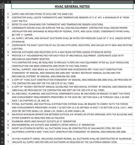
Having troubles keeping your MEP notes from Excel in Revit up to date? Schedule XL is the right tool for you.
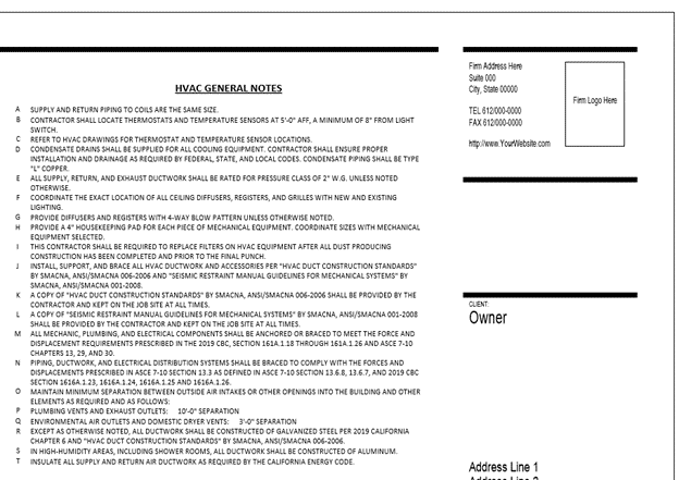
Schedule XL allows you to create schedule views (drafting view or schedule view) within Revit from your Excel worksheets. Simply create an Excel file with your MEP notes in the format you’d like and push that information to your Revit project.
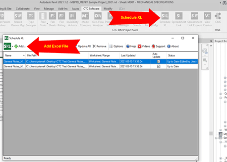
Within Revit, select the CTC Schedule XL tool and add your Excel file that you’d like to be placed in the project.
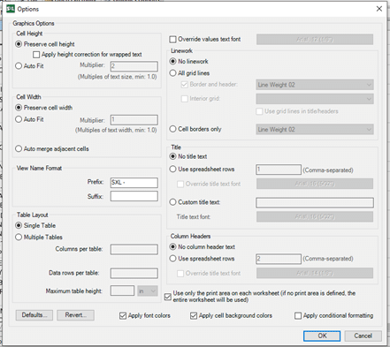
Once added, you can override/preserve any graphics or formatting of the Excel file
As you make your modifications to the graphics, select “OK” and Schedule XL will create a new Revit view for you. Place the view onto the desired sheet.
As your Excel notes update and change, you can use Schedule XL to verify if your project has the latest updated notes. Schedule XL has a “Status” feature to indicate if your Excel note files are up to date. With the “Status” showing “Out of Date”, simply click “Update” to apply the new changes.
Schedule XL is a great tool for including outside data from other sources (Excel) to be a part of the Revit environment. With a simple Excel to Revit workflow, you can get any information across to a project with minimal effort. Schedules can also be configured to automatically update when the Revit project is opened if the original spreadsheet has changed.
So, you need to work remote from the office and you have discovered it is a bit of a pain for production. Or, perhaps you have yet to discover the pains of extended remote work and you want to be prepared? CTC Software has tools to make all aspects of production more efficient, including the remote workforce.
The biggest delay when working remotely in Revit, after the project model access, is getting and loading content. The project model has been properly solved by Autodesk’s BIM360 eco system. Sadly, that system is not very efficient at holding the content and allowing it to be loaded into project models. This content loading process typically involves someone using a VPN connection to remotely access the office network, then browsing across that VPN connection. When the time comes to load family content it is rather slow, but even worse is when system families or typical detail views must be accessed. These pieces of content are stored in project models, and these models can be rather large. Opening and transferring settings from these models is extremely slow across VPN.
CTC has heard it said, “Well, I’ll just use Google docs, or Dropbox then…” Well, this may work, but keep in mind, small company libraries are about 1GB of content per Revit version so this could easily mean storing and syncing 4GB of Revit content, and this is estimating conservatively. Most firms have way more than that.
So, what is the solution? CTC Has a toolset called HIVE. It is tuned to manage Revit’s custom libraries but can also be used for any kind of content. Since we are discussing Revit here, understand this, HIVE allows easy google-like searching of the regular loadable families, System families, typical drafting views, Schedules, and even fully assembled sheets. This all can be done with very minimal setup, and users get the content they need on-demand. All they need is an internet connection. This would not require any VPN for the content stored in HIVE.
CTC has run demonstrations of HIVE from conferences like Autodesk University and BiLT. These conferences often have acceptable but certainly not speedy internet, and sometimes the internet at these events can be very unstable. While there, CTC often conducts HIVE demonstrations, browsing for any needed content with no perceptible delay.
What does this mean for you? Well, your BIM Management team can easily configure HIVE to host all needed Revit Content, and your workforce can access it from any workstation connected to the internet. They will need the internet anyway to work on BIM360, so the system requirements and connections are already in place for them to use HIVE almost instantly.
Contact your local CTC representative to get your trial of HIVE and understand how you can purchase this perfectly tailored solution for times just like the ones we currently find ourselves in.
I would like to point it out two tools that can make a big difference when designing roofs, the Truss or Rafter tool and the Extending to Core tool. They also affect the shape and size of the eave truss.
Revit offers to options to justify the roof and the reasons why is because the bearing condition is very different between the two. The Rafter or Truss option is only available if we choose the Pick Walls tool.
When we select Roof by Footprint, and the Pick Walls tool, we see at the Options Bar the Extend to wall core check box.
The diagram below explains the different roof configurations that result from switching on and off the Overhang Extend to Core option and the Rafter or Truss option. When the Extend to Wall Core is activated, Revit will measure the overhang from the core. When it is not activated, it will measure the overhang from the exterior face of the wall. Also noticed how the Truss and the Rafter connections change. The Truss sits on the Exterior face of the wall while Rafter sits on the interior face of the wall.
Another advantage of using the Pick Walls tool is to assure stability when editing the overhang. When we use the Pick Lines tool, Revit create a line that not attached to the wall. Notice that there is no option to change between Truss or Rafter. Below I draw a roof using the Pick Lines tool and another one using the Pick Wall command. See the difference when I change the overhang dimension.
Notice that when using the Pick Lines tool, the roof and the wall are not aligned and to fix that we would have to drag the roof manually. On the contrary, using the Pick Walls command, the roof remains aligned to the wall. Whenever is possible, it is best to justify the roof using the Pick Walls tool when creating the roof footprint. By doing that we are avoiding future issues, saving time and getting the most out of Revit!
Since my last post about the path of travel, Autodesk made a very useful update on the path of travel tool.
The path of travel was calculated automatically by Revit picking the start and end point. Now we have the ability to add waypoints along the path of travel. This allows us to drag the points and adjust the path. You can also delete the waypoints to restore to default position.
To activate the tool, simply select the path of travel. The tool will appear under the Modify| Path of Travel Lines. Select the Add Waypoint, click on the path of travel and drag it to adjust it. To delete it, select the Delete Waypoint and click on the point.
Many firms struggle to fully keep their Revit models healthy. There are manual, and tedious workflows that can be error prone.
Do you want to do a thorough health check of your model prior to sending it out? Exhausting time checking to ensure information is correct, accurate and consistent across the project team, and projects can be tedious. Let’s look at a few tools from CTC Software that can help you make this process quicker and more effective project to project.
BIM Manager Suite – Dimension Checker, Project Cleaner*, Type Swapper, Shared Parameter Manager, Family Processor, Import Link Manager
BIM Batch Suite – Family Loader*, Family Exporter*, Plotter & Exporter
BIM Project Suite – Model Compare, Spreadsheet Link
Problems We Face
We need to have, and should have standards
Standards can be hard to maintain
Standards can be cumbersome and tedious
Consistency can be hard to track manually
Workflow Process with 3 CTC Tools
Shared Parameter Manager – Much easier way to manage your shares parameters compared to the out of the box method. Browse your master shared parameters file and compare to a source file. Filter differences between the master and source file, and add, modify, delete, move, duplicate, and find/replace.
Family Processor – Able to make multiple changes to multiple families in batch to ensure the content’s schedules are consistent and accurate. Powerful when you are building a library, adding new content, or downloading content from manufacturers. Builds a summary health check file of each family so the BIM Management team is able to track new or changed content.
Family Loader* – Once the content is up to date and standardized by using Shared Parameter Manager, and Family Processor, you can batch load those specific fixed or new families in a project.
*For Free Tools, contact SolidCAD to discover and evaluate your current workflow in Revit and let us find the right solution for you.
A lot of people are still estimating on paper plan to quote their job on a project. So, why should they use Bluebeam for doing it? In fact, we’ve got the answer from the same people; faster, direct export to Excel, more precise than ever with the calibration integrated in the document (from Bluebeam or directly from the drawing software where the plan came from) and finally (maybe the most important) no printing.
So, what do you need to know about Bluebeam to start estimating?
In this article, we will see tools to be used in order to give you the basic knowledge to begin quoting on your PDF plans within Bluebeam.
(1) Calibrate your plan
The first step is to calibrate your plan. In order to be able to quote lengths and areas, you need to make sure your plan has been calibrated correctly and accurately to avoid any mistake (or at least, limit those mistakes)
For this purpose, we will have to set the calibration by selecting Measurements and then, Calibrate.
Then, we will use a measure already indicated in the drawing to calibrate our plan by using the side line as our guide.
When you finish tracing your calibration line between the 2 extremities of the side line, click again and a Calibrate menu will appear. Now, write the same length as indicated in your side line and you’re done. Your plan has been calibrated. Pretty simple, isn’t it?
You are now ready to start.
Note from the author: I always double check after calibration by measuring another sideline length to be sure the date I used was correct. It could happen a drawer changed manually a length to have a rounded number in place of the real length.
Most user rather use the calibration within Bluebeam instead of the scale indicated on plan because it’s more accurate.
(2 ) The Measurement tools and their purpose
Bluebeam has 13 default tools to do measurement. It’s more than what we need to estimate. I am personally selecting 3 of them to create my own tools set for estimating. You are free to choose depending of your need. In addition to those 3 tools, I also often use Dynamic Fill, but we will see that later.
Linear estimates (imperial / metric)
To be able to do precise estimates, we’ve got 2 choices: Length and Polylength.
I prefer to use Polylength for 2 reasons: I’ve got more custom choices that I can apply to my length and, above all, I can take of sidelines in extremities to be more readable and smooth (and you can’t do that with the regular Length tool)
Now that we choose our estimating tool for measuring length, we will need to think about what we need to quote. Usually, an estimator doesn’t quote on a single product or job. So we will use our Polylength standard tool to create our different custom tools set of products/jobs we will need to quote on.
On this purpose, trace a standard Polylength on your plan (picture below).
Then, in the customization quick menu above your drawing, you will be able to change color, width, line type… and finally, give a name to your custom Polylength and save it in a custom Tool Chest (you should have created before, obviously or select an existing one). For example, in steel estimating, people use to call their length as the type of beam they need to quote. This allows them to estimate on measurements AND count them at the same time. MEP sub-contractor are doing the same for HVAC duct or general pipping.
Once you finish customizing, save your custom tools by clicking on Add to Tool Chest and select the one you have been created.
You can now use the same line to create all products / jobs you need to quote and populate your tool chest by changing name, color, type of Polylength and add it to the right Tool Chest. It will not overwrite your first custom tool already created.
Note from the author : This stage can be a bit long but once you’ve created all needed tools, your job will be really more easier than ever. The more developed your tools are, the less time you will spend after to organize your data and get your result. But, if it is your first bunch of tool, don’t overthink it too much. The more time you will use Revu, the more you will know and the more custom your tools will be.
3. Area Estimate (square feet / square meters)
For this part, we will use exactly the same process than previously done for Ploylength but we will do it by using Area standard tool.
On a similar way, we will create areas to represent what we want to quote and name them. For example: Floor, Concrete Slab…
Then we will customize them with different colors, fills and even being able to include hatch in them. Finally, we will save them in a tool chest the same way you did with Polylength.
This is the conclusion of the first part of Estimating with Bluebeam. In the next post, we will see how to create layers and how to use them smartly and how to create, customize and use columns in Markup List to create quick and easy estimates.
Let’s talk about data corruption in Revit. In this post I will look at these 4 points:
File crashes before opening
Crashes when opening a new view
Looking for corrupt families
Higher level investigation
As always you should make sure you save a copy of your file for testing while trying to resolve corruption issues.
File crashes before opening
Sometimes a file cannot open because of a simple issue that can easily be overcome. Each of the following actions have the potential to get past a different issue. If your file crashes when you try to open it ask yourself:
Can the file be opened with or without audit checked?
Will the file open without the worksets loaded? Can I narrow it down to a specific workset that keeps the file from opening?
Can I open the file in a different build, or a newer version of Revit?
Sometimes new name allows you to bypass the issue, copy-paste file to new location
Isolate the file from the network save to a location where the links cannot be accessed.
Crashes when opening a new view
If your file crashes when you try to open or create new views, try these suggestions:
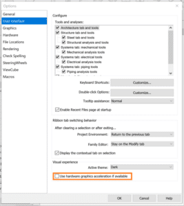
Turn off hardware acceleration and try each location one at a time.
Reset Revit settings
Customized settings are stored in the app data folder, when removed from this location the defaults are regenerated.
Repair the installation
This won’t change any user setting.
Open Revit without add-ins
Locate the following folder: C:\ProgramData\Autodesk\Revit\Addins\[Version].
Temporarily move the add–in files from the folder above to another location.
If any of these work for you take note, this is where the issue resides and you’ll want to know the exact cause whenever possible.
Looking for Corrupt Families
Sometimes the behavior you see in a file is caused by corrupt families follow this process to identify corrupt families.
Save a copy of the corrupt file
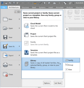
Open and save all families as a library, this process will fail when it reaches the 1st corrupt family.
Record the family named on the bottom left hand corner of the screen & delete the family and run again, repeat until the process completes successfully.
Open the original corrupt file and reload all the families on your list with versions that predate the corruption. If you’ don’t have a previous version of the family, you’ll need to recreate them.
Higher level investigation & troubleshooting
Many issues can also be fixed by returning to Revit’s original settings. Try these steps one at a time, testing the file after each change.
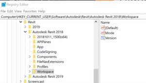
Rename the .INI file (_old) which is in the AppData Roaming folder.
When these folders/files don’t exist, they are recreated the next time the user opens Revit. Be sure rename and not remove these files/folders, as they will server as backups for the user original setting including keyboard shortcuts and font maps.
Happy Reviting!
Be sure to check my other videos in this series for more information.
While you wait why not follow us @SolidCAD on Twitter, check out our other videos on YouTube, and see what our experts have to say on our BIM Blog!
Usually Tags are added separate from the Components we place, but in certain situations the “tag” needs to be part of the family. To push this further occasionally a request is made for flexibility in the placement due to text overlap.
This post explains how create a family with a built-in label with adjustable positioning.
Prepare the Model Family to Receive the Label
Open the model family that requires the built-in label.
Create a vertical and a horizontal Reference Line to mark the center of the default label location.
Create a vertical and a horizontal Reference Plane offset slightly from the reference lines. These will be the anchors for the label. Both Reference Planes must be set as “Not a reference” for the grips to show properly in the project.
Dimension between the new horizontal references, and the between the new vertical references. These dimensions need to be assigned separate instance parameters. To allow the label to slide in the project.
Choose which existing reference planes you will Align and Lock your anchor Reference Planes to. I prefer to lock them to the planes the model uses as origins. The plane you lock to must be stationary (not controlled by an instance parameter), the label will not be able to cross the horizontal anchor plane.
Save the family.
HINT: To make working in a complicated family simpler follow a few best practices.
Set the origin planes, then pin them.
Name reference planes clearly and remove temporary planes ASAP.
Dimension to the reference planes, not geometry.
Flex the parameters of the family before adding geometry.
Geometry to be locked to reference plans after confirming the parameters work as expected.
Create the Label Family
Using the Generic Annotation Family Template, create a new “label” family.
Place a label, you will be prompted to create/assign a parameter to the label.
Edit the label type properties, so the text size & style meets the company standards.
Save the label & load it into the model family you started with.
Combining the Two Families
Place the label family near the geometry in the project.
Align the horizontal reference in the label to the horizontal Reference line, and lock.
Align the vertical reference in the label to the vertical Reference line, and lock.
Select the label and Edit Type, associate the Family Parameter for the Label to the Family Parameter in the host family which will control the text, often Description or Type Comments.
If you have chosen to have a visibility Parameter to control the Label Visibility, associate those parameters to one another as well.
Using the Family
Save the Model Family and load into a blank project to test the flexibility of the label location.
Select the family, the grips for the label location will become visible. Slide then around in turn.
NOTE: Look for unexpected changes to the geometry or the overall placement of the family, this indicate the need to change the anchor alignment.
Path of Travel tool is a new feature in Revit 2020 that determines the distance between two points on a floor plan. By selecting a start point and an end point, Revit automatically creates the path and calculates the length and the speed of the travel based on an average walking time. The tool also recognizes obstacles such as walls and furniture and create a path around these model elements. The tool will ignore some model elements such as demolished elements or elements that are hidden in the view.
Some other categories can also be customized under the Analyze tab – Route Analysis Settings.
Notice that by default the doors are not considered obstacles.
You can also set an analyze zone and determine the top and bottom offset. Any object in this range will be considered an obstacle and the path will avoid them.
Path of Travel
To use the Path of Travel tool, open a floor plan view and go to the Analyze ribbon tab and select Path of Travel on the Route Analysis panel. Revit will ask to pick a start point and an end point.
Once we have selected the end point, an automatic green path line runs along the building. Since we can tag the path information, I placed a tag to read the length and time parameters.
The tool can also be updated in case we add a model element on the way. To update the path, select the path you want to update and under the Modify | Path of Travel Lines click on Update.
Notice that it also updates the tag.
If we select the path created and look under properties, we can find the instance properties calculated by the path. These are reporting parameters and when you modify the path Revit will redo the calculation. Notice that the Path of Travel is a detail line which means it is view specific. It is important that you create this in the view you wish to see it in, and it will not need to be filtered or hidden from other views.
Reveal Obstacles
This tool is very useful to figure out why the Path is not behaving properly and understand which elements are being considered as obstacles.
After toggling it, all elements analyzed as obstacles will display in color and the rest will display in halftone. The categories can be changed at the Route Analysis settings.
Schedule
We can also schedule this information and set filters to analyze the content and see if it is code compliant. The Path of Travel Lines will be under the Lines category.
Here is a sample of a schedule with all the parameters that are available. On my example I set a filter to highlight in red the paths that go over 30m.
Filters
We can also set filters to easily identify these paths on a floor plan view and make changes if necessary. In this example I set the filter to override the lines that are greater than 30m.
Potential Issues
One last thing I would like to point it out is that this path graphics are not fully customizable. We can change the line style from solid to dash for example, or create a new line style, but you cannot customize the arrow and dot at the start and end point.
The other aspect that we cannot control is the distance the path takes around an obstacle. The calculation of this distance occurs in the background. It takes in consideration the width of a typical person and body sway while walking. If you want to read more information about the path travel calculation click here.
Conclusion
It is impressive in how automatic and smart the tool is. Even though there are limitations on how much customization we can do with the tool, it is very exciting the fact that it can goes around objects and that it automatically updates when a change occurs, also how you don’t have to draw the line yourself, it does it for you.
Down below are BIM Project’s Suites best FREE tools:
(1) Quick Select
Gives users the ability to build or filter selections of Revit objects by specific categories or parameter values. For more click here
Revit Filter Tool
vs Quick Select Tool
(2) Renumbering
Provides a fast and simple way to renumber your rooms and doors. Auto-swapping avoids duplicates. Alphanumeric sequential numbering. Add separators and suffices to room and door numbers. For more click here