fbpx
  • Vault Pro 2024, new job processor functions!

    With the release of Vault Professional 2024, Autodesk add two new job process into their job processor tool.

    STEP and DXF are now added to the current PDF functionality. These new functionalities could be done by lifecycles states or manually on demand.
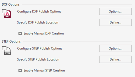
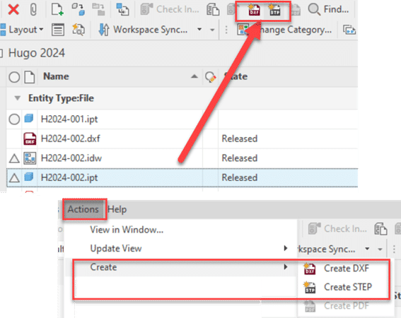
    On demand function will appear into the standard Vault Toolbar or also into the action menu
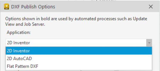
    DXF Options is available for 3 file types, 2D Inventor, 2D Autocad and Inventor 3D Flat pattern.
    STEP file option is only for Inventor .IPT and .IAM files.
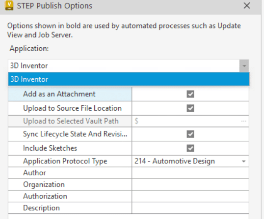
    As the actual PDF option, you can specify publish options inside or outside the Vault. But take note that for the DXF Flat pattern, it’s impossible to specify a custom .ini file to generate the DXF with your custom configuration! We expect that this functionality will be added in a next available service pack or a possible workflow to modify the generic setup. I will keep you updated with another post when a solution will be available.

    For Lifecycle change state options you will find these options into the transition action Tab and the three small dots on the “Synchronize properties and update the selected file types using the Job Server”.
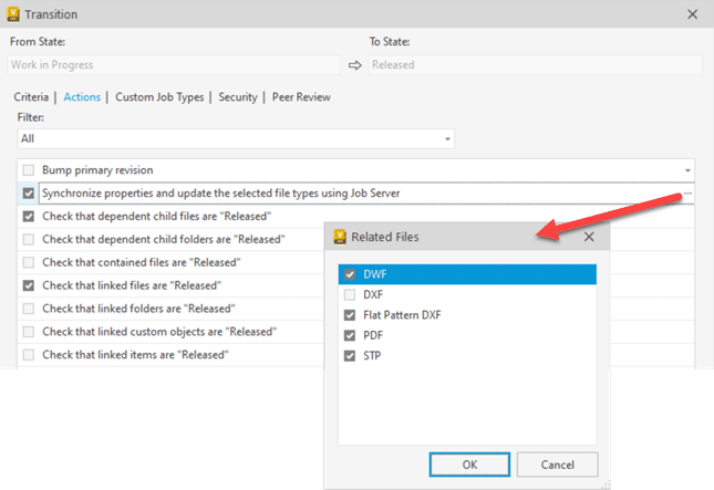
    Take note that if you choose the two DXF options you will have by default two .DXF files. By default the Vault naming rules are the “filename + actual file extension + .dxf”.

    Ex: if you have a file name as part 123.ipt with drawing 123.idw you will have 123.ipt.dxf and 123.idw.dxf.

    If you prefer to don’t have the original file extension into your .dxf, please don’t add two DXF options in same time.


    Now, how to change the DXF or STEP file naming default?

    As the actual PDF, you simply need to modify or add this following line into the JobProcessor.exe.config file.

    1.1)    <add key=”DesignRepresentation.Naming” value=”\.(idw|dwg|ipt|iam)$/&lt;_name_&gt;”/>

    I suggest this link to see more about file naming options: https://help.autodesk.com/view/VAULT/2024/ENU/?guid=GUID-F05BFEAF-A362-4070-BBA6-F3A74602967E

    The suggested line in 1.1 will create STEP, DXF & PDF without file extension. And it will be applied for .ipt, .iam, .dwf and .idw files.

    It’s why you see in yellow below the value added in the option (not mentioned into the Autodesk help)
    value=”\.(idw|dwg|ipt|iam)$/&lt;_name_&gt;”/>

    Example of the result:

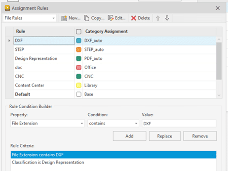
    All files generated by the job processor (PDF, DXF & STEP) are Design Representation and you can easily assign specific categories to them.

    All these files have a specific property because they are created by the Job Processor. The property is “Classification” and type is “Design Representation”. So if you add this into your rules and the file extension, you will be able to automate other category for STEP, DXF or PDF not generated with the job processor.
    Enjoy the new tool and see more info into the Vault 2024 help!

    Hugo Trepanier

    Starline Windows

    Success Stories

    Starline Windows

    Starline Windows is an industry leader in the design and manufacturing of architectural aluminum window systems, as well as residential vinyl windows and doors for over 50 years. They have completed thousands of contracts and worked on multiple award-winning buildings across North America.

    Their commitment to customer service is and always will be a pillar of their success. With a highly experienced team, they work with their customers on every stage of the project, from initial consultation and design through to installation.

    As part of their business, they work with architects to design structural façade glazing features, provide on demand customized manufacturing capabilities in-house, and have a crew to construct and install windows and doors on site.

    Rising to the Challenges of the Industry with Vault, Revit, Inventor, Autodesk Construction Cloud and PLM software!

    The Challenge

    Today’s push for remote work and custom designs have exposed some logistical difficulties for Starline Windows. To continue providing services in every step of the process, there is a constant need for better tracking and traceability of project commitments, product manufacturing and installation life cycles. Starline Windows faces business challenges that many other businesses face such as (1) lack of design collaboration engagement with external architects and contractors, (2) lack of design revision visibility for field personnel, (3) lack of project cost clarity, (4) limited data transfers between operating systems from the office to the field and (5) lack of cross department visibility in their overall coordination for logistics management.

    First and foremost, Starline Windows has always sought to improve granularity and accuracy related to their costing takeoffs. Due to software limitations, they often had to manually manage their takeoffs and Bill of Materials (BOM). This resulted in other departments working with manually generated data reports on a regular basis which are prone to human error.

    The Solution

    Starline Windows first connected with SolidCAD in late 2019 to provide insight to the concerns and challenges they have been facing. SolidCAD helped organize a detailed plan that would organize their pain points and provided a solution into four key phases:

    PHASE 1: Improving their Product Lifecycle Management

    Starline needed a solution that would better manage their projects for employees working in office and provide visibility over the progress of those projects. SolidCAD implemented Fusion Lifecycle Manage PLM to achieve this and set-up automatic notifications to any team members, to ensure they are always staying on track with any project changes.

    PHASE 2: Enhance their Design process with Revit and Inventor

    Outside of the issues with their workflows, they also struggled with their current 3D design process. Starline was looking to better automate their workflow between their Revit models and how they would be imported into Inventor for further manufacturing design. SolidCAD automated model creation based on their Revit schedule into Inventor, speeding up their entire design process.

    PHASE 3: Document Management with Vault

    With the seamless connectivity between Revit and Inventor, it was important that all teams were working with latest design files. It was critical to integrate Autodesk’s Vault Professional to ensure that everyone at Starline was working from a central source of organized data. As a result, Starline noticed an immediate improvement in being able to easily manage the revisions that slowed them to automatically tracks changes, maintains past file versions, and capture the entire history of their designs. This also reduced the amount of time and rework that often happened when they worked with outdated files.

    Most importantly, Starline wanted a seamless integration between their newly implemented Fusion Manage PLM system and their Autodesk Vault, which SolidCAD was able to achieve through a managed service delivery team.

    PHASE 4: Collaboration on field and in office with BIM 360/Autodesk Construction Cloud

    Although it was important for SolidCAD to help Starline Windows integrate systems that would better connect their internal departments and processes of design management, they also needed a solution to collaborate with their on-field and in-office employees. SolidCAD introduced Autodesk Construction Cloud (ACC) and specifically Autodesk Build and integrated it with their PLM solution to manage their Revit models and provide project visibility. Starline Windows was able to easily record, capture and manage the exchange of design data between their project teams and on-field contractors, ensuring that all teams were working from the latest model designs produced in-office.

    The Results

    Over the past year, SolidCAD has successfully implemented these various solutions and continues to support Starline throughout each phase. Although many of these processes do not give instant results, Starline Windows have already seen initial improvements and are on track to many more successes in later stages of their journey, such as:

    • Improved project management for office staff, allowing for visibility over processes and projects.
    • Introduced Revit and Inventor to streamline their design process.
    • Automation between Revit and Inventor allowed for automatic model creation based on Revit Schedule.
    • Implementing Vault and connecting it to PLM software has led to accurate data sharing to be available remotely.
    • Automation between ACC and PLM software meant that projects can be visible in personal productivity applications as well as project and organizational management allowing for improved resource management from beginning to end of projects.

    To learn more about the solutions implemented and the ways that Starline Windows have recognized and overcome some of the biggest challenges facing their industry today, check out the recording from our online event, “The Digital Thread – A Customer Journey” with Catherine Walmsley, Business Analyst at Starline Windows and Autodesk’s Queen of Prefab, Amy Marks.

    Testimonial

    We first reached out to SolidCAD to ask for an initial consultation after having searched worldwide for experts in design to manufacturing automation. The management team at SolidCAD listened to our biggest challenges and helped connect us with multiple experts in several disciplines to answer all our questions, however technical and detailed they became.
    SolidCAD not only helped the Starline Windows management team formulate a strategic plan to increase our ability to deliver productivity tools to our users while simplifying change management; they also provided key resources to configure and integrate new systems, onboard new users and train key players to help us accomplish our goals in record time.
    -Catherine Walmsley,
    Solutions Analyst at Starline Windows

    Products & Services Used

    Similar Projects

    Rutherford 120

    Who is Strasman Architects?

    Architecture is not merely about designing structures; it's an intricate blend of art and science that shapes the built environment, reflecting the cultural, social, and technological nuances of its time. Most importantly, it’s a collaborative…
    Paper Excellence

    PAPER EXCELLENCE

    Paper Excellence is a diversified manufacturer of pulp and paper, including printing and writing, packaging, and specialty papers. We believe in the enduring value of wood-based products in global markets and have built a large…
    Western University

    Western University

    Western University is one of Canada’s top research-intensive universities, located in London Ontario. With over 9 million square feet of space in 100+ buildings, Western University’s Facilities Management department is responsible for the planning, development,…

    Tons of new goodies for Fusion 360 CAM

    Since I last wrote here, there have been big, big changes to Fusion CAM (excuse me: “Fusion Manufacturing”). These changes range from completely new (and it needs to be said, very useful) machining strategies, to significant progress in the implementation of probing technology, to new love for turning, and to subtle but much-appreciated improvements to the user-interface.

    The biggest changes are contained within the Manufacturing Extension, a new subscription add-on for Fusion CAM. The idea is that while Fusion CAM (and Inventor CAM and HSMWorks, for that matter) is a modern and very competent CNC programming solution that can make short work of most jobs at a VERY attractive price, there are some customers that require still more power and that are willing to pay a little extra for it. Mold makers are a good example. In the past, the limited multi-axis toolpaths of Fusion CAM did not quite meet their needs. With the new Steep-and-Shallow strategy as well as toolpath trimming / direct editing (both technologies gifted from PowerMill), that has all changed. The Manufacturing Extension also opens the door to surface inspection and on-machine verification, a very hot button for anyone trying to increase efficiencies and get an advantage. Throw in automatic hole recognition technology (thanks, FeatureCAM) and a new Rotary multi-axis 3D milling strategy (this one is all Autodesk), and there is something for everybody. How much for these new goodies? 125 Cloud Credits ($125 USD) per month, month-to-month.

    And those other improvements? How about a new tool library interface? The old one definitely was a little clunky. And for those of you who make extensive use of user-templates to capture their best practices (why isn’t everybody?), how about a new interface that will allow you to sort and better manage everything?

    I haven’t talked about turning yet… It can be said that while Fusion CAM  / HSM CAM has traditionally been a competent turning solution, most of the R&D over the years has gone into making it a premier milling solution. But a dedicated turning team has now been brought into the development team, and turning is now getting the love it has always deserved. In my next blog, I’ll list all the recent changes (it’s a very long list of small but significant changes). What’s more, we are promised many more such improvements throughout the year, including something called Adaptive Turning that sounds very promising.

    Please note that the Manufacturing Extension is free to use right now through June 2020. So, by all means, give it a spin! Several of the other new features are available through the preview mode: just activate what you want under Preview Features in your Preferences; everything is quite stable.

    Now, it is quite apparent that Autodesk is turning Fusion into its premier CAM solution. That’s great news and we welcome all the improvements to an already-great CAM. However, if you are a user of Inventor CAM (or HSMWorks), don’t hold your breath for things like Steep-and-Shallow. Instead, Autodesk would rather you fire up the Fusion 360 entitlement included with your CAM. And to make it easier to use two platforms in parallel, recent changes now allow Fusion to play extremely well with Inventor and even SolidWorks.

    Dynamo for Autodesk Fusion 360 – Made Simple

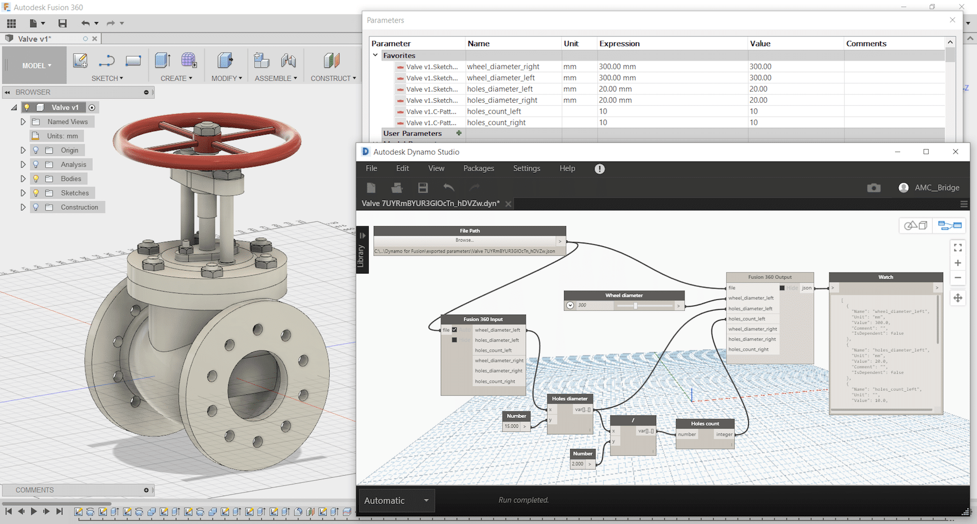
    Dynamo Studio is typically associated with Revit; however, it offers a fantastic platform for algorithmic-driven design and easy parameter manipulation in Fusion 360. It also features great T-spline and surface support for complex geometry creation, for those wishing to bring a degree of parametric control to their surfacing with ease.

    The add-in supports a bi-directional data exchange between Fusion 360 and Dynamo Studio, allowing users to create visual logic for Fusion 360 parameters update. It can be downloaded here: https://apps.autodesk.com/FUSION/en/Detail/Index?id=74731490955641349&appLang=en&os=Win64

    It provides an ability to use a visual editor environment to modify Fusion 360 model parameters, view and use them in complex logical graphs. Fusion 360 parameters will be automatically updated from Dynamo Studio using custom input and output nodes.
    Dynamo for Fusion 360 Supports Dynamo Studio 2017 version: 1.1 – 1.3.

    The benefits of using Dynamo with Fusion 360 are:

    • Very complex and rapidly reconfigurable T-Spline surfacing is
    • Parameter driven components can be modified live using sliders to adjust
    • Parameter driven components can have logic integrated to link different parameters and make automatic adjustments according to conditional
    • Parameter driven assemblies can be modified live and can adapt if setup
    • Parameter driven assemblies can have logic integrated to link parameters from different components to respond to changing geometry according to conditional

    One of Dynamo – Fusion 360 Workflows is called “Synchronous workflow”. It is directly manipulating parameters listed in the parameter table in Fusion 360. This can enable rapid reconfiguration of assemblies and components by using sliders, or logic can be incorporated to describe relationships between geometry. If you have not tried, here are some simple steps to try:

     Step 1: Create a simple Fusion part with some name parameters as shown:

    Step 2: Save and name the part as “Dynamo-Fusion”

    Step 3: Go to Tools -> DYNAMO FOR FUSION to run Dynamo


    Dynamo will create a same name parameter file with extension “.json” that contains all extracted parameters from Fusion 360 part and stored under:  C:\Users\ (your username) \AppData\Roaming\Autodesk\Autodesk Fusion 360\API\AddIns\Dynamo for Fusion\exported parameters\

    Step 4: In Dynamo’s search bar, search for “output” and insert “Fusion 360 Output” node. Repeat search for “Slider” and insert “Number Slider” node.


    Step 5:
    In Dynamo, connect File Path to “Fusion 360 Output” and “Number Slider” to any parameter and set Min, Max and Step. Use the slider to size or adjust the features.


    If you would like to manipulate other parameters, then just add more sliders. Simply select the slider node and use Ctrl+C to copy and Ctrl+V to paste it. After that you can customise each slider values (Max, Min, Step) and connect it to any of the parameters and watch the part update. You can even connect a slider to more than one parameter (i.e. to make a square cut).

    Using Dynamo with Fusion360 can be fun and simple. Try it and have fun with Dynamo for Fusion 360.

    Frame Generator End Caps in Inventor 2020

    In the 2020 release of Inventor, the Frame Generator Design Accelerator received a number of minor enhancements as well as one of significance that likely has users asking how they ever lived without it. You can now create and insert end caps to a frame member within Frame Generator.

    Here’s how:

    First; you must have the Custom Content Center Library installed in order to use this feature. Learn how to do that here. Once you have frame members ready for end caps, follow these steps to quickly create and add the components:

    (1) Select “Insert End Cap” on the Frame panel of the Design tab within your assembly;

    (2) Select the end faces of the members you wish to apply end caps to.

    (3) Choose the placement: Inset, or outward

    (4) Choose the profile style: Filleted, Chamfered, or Sharp corners

    (5) Enter the Chamfer/Fillet size (if applicable), Thickness, Inset (or Offset) distance & Rotation angle

    (6) Select the desired part properties, then OK (or “+” to add additional end caps for different tube profiles without exiting the property panel)

    (7) The end caps are created as members of the frame assembly and the file naming can be controlled in the same way (using “File Naming Defaults” in Application Options). Inventor recognizes identical members upon creation and reuses the end cap files where possible, rather than duplicating them.

    End caps can be edited or reused like frame members, using the right click menu in the model browser (“Edit with Frame Generator”)

    Customizing the Inventor Marking Menu

    A few years ago, Autodesk introduced context-sensitive radial menus called Marking Menus, in Inventor. These menus provide a quick and visual way for users to select the most commonly used commands in each environment. Over the years every-day users have no doubt become quite familiar with these menus and the available commands, but did you know you can customize it?

    By default, Autodesk has placed what they believe to be the most common commands in this radial menu however, you know as well as I do that from company to company and even desk to desk, everyone uses Inventor differently. The following are the quick and easy steps to customize this menu.

    How to do it:

    On the Tools tab in the Options pane, the “Customize” button will open the dialog box that lets you modify the 8 commands in the radial menu for a given environment and associated sub-environment. From 2D Sketch to Weldment and everything in between, you can put your favourite commands right at the tip of your mouse pointer.

    Choose the environment and sub-environment you wish to customize the menu for. Next, select one of the eight radial menu options that you want to change (in this example we are changing the “Pattern Component” command in the standard Assembly environment).

    In the menu on the right, search or scroll down to the command you want to add and simply click on it to replace the selected option (iProperties, in this example). It’s as easy as that!

    A

    lso; starting in 2018 Inventor began giving users the option to migrate these (and all other) custom user interface settings when you upgrade to newer releases. So, you no longer need to worry about starting from scratch!

    Why is it called the “Marking Menu”?

    In addition to customizing where your favourite commands are on the right click menus, did you know you can also right-click-drag to the command, without ever actually seeing the menu? The pointer will create a “mark” as you drag your mouse to the location of your desired command, as shown below. This will require some practice but could become quite handy over time when the location of the commands in the radial menu becomes second-nature.

    PART 2 : Bill of Materials (BOM) Transfer from Vault to Fusion Lifecycle 

    This is the second in a three-part series of Fusion Lifecycle videos. This video, will focus on the Bill-of-Material transfer from Autodesk Vault Professional to Autodesk Fusion Lifecycle.

    Vault Pro and Fusion Lifecycle can be integrated allowing data to move between the two systems. When Designers and Engineers have completed their work in CAD and Vault Pro, they will Release the assemblies.  The Bill-of-Materials is then extracted from Vault and transferred to Fusion Lifecycle as an Items BOM.  In Fusion Lifecycle, the BOM can be managed by adding or removing items.  When complete, the BOM is advanced to the Approval Stage using Fusion Lifecycle’s Bill of Materials Management capabilities.

    Porcupine Engineering Services Inc.

    Success Stories

    Porcupine Engineering Services Inc.

    Porcupine Engineering is a professional services firm providing clients with a comprehensive range of services including multi-discipline engineering (conceptual and detailed design), project management, planning & scheduling, feasibility studies, cost estimates, procurement, shop inspection & field services, construction management, commissioning and start-up, and production & maintenance support.

    With offices in Timmins and Sudbury, Ontario their team is composed of professional engineers, project managers, technologists, technicians, coordinators and support staff.

    Project Profile

    Challenge

    Porcupine Engineering is committed to providing their clients with the highest quality and up-to-date field services and support.

    Porcupine Engineering turned to SolidCAD in need of a full-service package that would integrate all software solutions they invested in as well as provide customized training and on-going support for all its staff members. Their goal was to incorporate an improved design strategy that would ensure value and efficiency to their clients and their projects.

    The firm began with the purchase of Autodesk software solutions, such as: AutoCAD Plant 3D, AutoCAD P&ID, Revit Structure and Inventor. Prior to their switch, they realized an increase in the use of 3D modeling and client expectation to have projects delivered as a 3D model.

    Originally, Porcupine Engineering produced many of their designs as a 2D model, which would often be misinterpreted by their clients— often causing rework, overall effecting the efficiency of their services.

    Solution

    In order to reduce mistakes and eliminate rework, implementing a comprehensive range of services that are both cutting edge and up-to-date with the changes that are happening within the industry become a priority.

    SolidCAD initially provided a presentation and discussion to uncover the existing workflow, than create and deliver a complete customized training package that would include all their technological investment in; AutoCAD Plant 3D, AutoCAD P&ID, Revit Structure and Inventor.

    Initially, the firm began with training for both AutoCAD Plant 3D and P&ID, but after successful preparation with the software and staff, Porcupine Engineering sought out SolidCAD to expand their customized training and include both Autodesk Revit Structure and Inventor into their existing workflow.

    After the execution of this full customized training program, implementation and on-going support, Porcupine Engineering and their clients had better understanding of the design and project when rendered as a 3D model than previously as a 2D design. The firm realized that by transitioning their projects into 3D models, and creating comprehensive workflow that included a wide-range of Autodesk Software— ultimately reducing errors and rework that would often happen during the design process.

    Results
    • They provide comprehensive services and solutions to their clients with less people, because their staff was now trained in wide-ranging understanding of multiple software solutions.
    • There has been a significant decrease in errors because 3D modeling has eliminated the revision process— helping designs get approved faster by clients.
    • It has reduced the time spent on rework to correct previous errors of designs and projects, and ultimately increase efficiency.

    Gold New Strip Circuit

    After SolidCAD’s customized training, Porcupine Engineering Services Inc, are able to provide their clients with all-inclusive services, better serving their client’s needs! Down below is an example of one of their projects for the northern Ontario’s gold producer.

    Project Description

    A northern Ontario gold producer was investigating the possibility of installing a new larger strip circuit for their mill.

    Firms Mandate

    Porcupine Engineering Services (PES) provided a Feasibility Study covering the technical and capital cost estimate considerations of the new strip circuit installation. The key components of the study were:

    • Flowsheets
    • P&ID’s.
    • General Arrangements of the new installation c/w 3-D model.
    • Single Line Diagram.
    • Control Topology.
    • Specification and selection of mechanical equipment.
    • Capital Cost Estimate (+/- 20%).

    Products & Services Used

    • Customized training for AutoCAD P&ID, Plant 3D, Inventor and Autodesk Revit Structure
    • Integrated the use of Plant 3D, P&ID and Revit into their existing unified workflow
    • SolidASSIST: On-going tech support during the transition and integration of software

    Similar Projects

    Énergir

    Public transportation – buses, trains, subways, and more – have a wide range of complex assets that are both mobile and stationary. Upgrades, expansions, and new assets become intricate engineering projects involving a broad array of[...]

    The City of Barrie

    The City of Barrie (“the City”) is a municipality located in Central Ontario, just over 100 kilometres north of Toronto. Barrie is in Simcoe County, on the shores of Kempenfelt Bay, which is the western…

    Société de Transport de Montréal (STM)

    Public transportation – buses, trains, subways, and more – have a wide range of complex assets that are both mobile and stationary. Upgrades, expansions, and new assets become intricate engineering projects involving a broad array of[...]

    Common Tech Issue of the Week #5 – Inventor Edition

    Cannot Hide Components in Assembly View in Inventor IDW File

    Issue:

    I cannot hide individual components in my existing assembly view in Inventor IDW file.  When I right-click on the part I would like to hide, the Visibility command is disabled:

    Solution:

    The reason why the Visibility command is disabled is that the assembly view was created with Associative option checked making it linked to a Design View Representation.  What you need to do is to turn off that option.

    Follow these steps:

    1. Right-click on the view and select Edit View command
    2. Turn off Associative option in the Drawing View dialogue box.

    SolidCAD
    3. Right-click on the part you would like to hide either in the view, or on the Model Browser and select Visibility command.
    SolidCAD
    4. The part is hidden in the view.
    SolidCAD