Need for data analytics is growing rapidly within the AEC industry. I have clients that tell me about the work, effort, time and most importantly money they have lost because they did not understand the reasons behind a project or a model being corrupted.
CTC Software makes tools to make sure these errors don’t occur. Specifically, a tool that logs data; Project Activity Logger.
There are some challenges to become a data driven organization, and CTC has the solution.
Common Challenges
Aggregating statistics and data of activity in on-going Revit projects
Detecting problems encountered as projects progress
Generating accurate and complete reports of current workflows, resources and expertise
Solution – Project Activity Logger (PAL)
Lightweight background capture of key performance indicators for Revit projects
Real-time availability of data on work-shared projects
Data stored allows easy connection & visualization with popular business intelligence software
Source of ROI – Return on Investment Realized
Flexible licensing & highly competitive pricing- get up and running with lower investment than similar products
Proactive and ongoing project analysis- make informed improvements before problems escalate
Optimize workflows, schedule resources and identify training opportunities for future projects
If you are a data driven firm or looking to get there. Contact SolidCAD to assess your current Revit workflow and understand what other firms are doing in the industry to get ahead.
Model Compare, in the BIM Project Suite. This tool can compare to iterations of a Revit model. Very useful to see “what’s changed” in very great detail. Thus if they are estimating, or looking for coordination issues, model compare is an excellent tool that many of our contractors use.
Spreadsheet Link, in the BIM Project Suite. This tool can push and pull data to and from Revit and spreadsheets. Very useful in estimation processes, and also if they ever need to push commissioning/installation/facility management data back into Revit objects in a project.
Fab Sheets, in the BIM Project Suite. This tool was actually created specifically for contractors who self-perform concrete work. If they do, or create any type of construction sequencing drawing/pour sets, this tool could be a huge time saver.
Project Cleaner, in the BIM Manager Suite. This tool is free. It helps to clean up models coming in from other parties, blowing away things like working views, or “all views, not on a sheet” which is a common desire of general contractors. This solves a few things. One, it makes the Revit project file faster performing. Two, by blowing away all the “junk” the designers left behind, it makes navigating the project in Revit easier.
Dim Checker, in the BIM Manager Suite. This is a really cool tool. It finds out where designers might be “lying” in a dimension.
Sometimes designers and engineers do not feel they have time to properly coordinate modeled object positions
Too frequently this leads to overriding dimension values in very dirty ways, mimicking the days of AutoCAD workflows
Unfortunately, these are rarely found and more rarely repaired, and can cause HUGE headaches for contractors and increase risk.
The DIM Checker allows these dimensions strings to be found and reports generated to allow the team to easily repair and coordinate these dimensions where appropriate
Plotter & Exporter, in the BIM Batch Suite. This tool runs on a nightly, or specified schedule to do all your exports for you. NavisWorks, PDF, DWG, whatever else you might need, automatically.
Sure, generating PDFs can happen from Bluebeam, but what about everything else
DWGs, Navisworks files and others often must be exported for other consultants and partners
Instead of doing this from multiple places, use Plotter/Exporter to single click export all the needed files
Have them exported where you want, named how you want with the exact settings you want.
Instead of manually triggering exports, try scheduling this so it can happen after hours and be ready for you when you walk in the office
Last but not least:
Import & Link Manger, in the BIM Manager Suite. Loading, and reloading links and imported files for coordination happens all the time. Waiting for Revit to link in everything, or to find where a link or import may, or may not be working is a pain.
All too frequently files are improperly linked or imported into production models
While Revit does allow minimal management of links, there is no easy way to find and fix imported AutoCAD files
ILM is critical to the regular maintenance of models by finding and fixing imports and update link settings in a simple interface
To watch our previous webinars on BIM Project Suite click here!
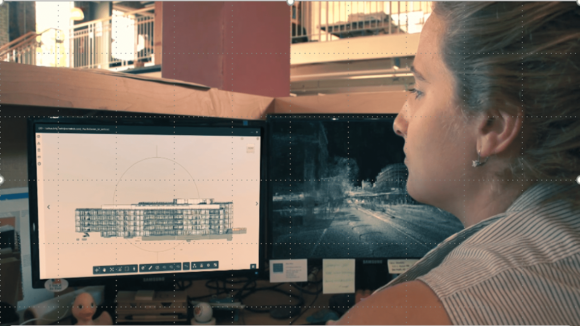
In case you were unable to attend SolidCAD and CTC’s webinar last week here is what you need to know…
Shawn Zirbes, a Guru for everything CTC, uncovered how the BIM Project Suite allows Autodesk Revit users to automate routine tasks, manage large numbers of content files, generate database information and much more in a lot less time, all within the Revit environment.
BIM Project Suite is meant for everyday users of all skill levels and used by firms of all sizes. To learn more about the some of key functionalities of the suite, watch the full webinar on our YouTube Channel.
Many engineers do not realize the power of Revit and prefer to trust the process of designs they have been using for years, such as Excel, manual calculations or their company templates. In fact, they have implemented Revit solely for the purpose of producing construction drawings. They miss the point that Revit can be used for improving performance and collaboration, not only for the drawings to look correct on paper.
In reality, engineers use Revit in conjunction with other third-party software. However, this disconnects the Revit model and calculations, lowers the level of accuracy and results in multiple recalculations.
In fact, Energy analysis is easier to perform in Revit than in any other program. Using Revit for heating/cooling calculations ensures that any changes that were made in the architectural model will be reflected in energy calculations. If you plan on performing energy analysis in Revit, you must define Energy settings, as well as spaces/zones at the beginning of the modeling. To do so you must verify that all spaces are set up with space elements (shafts, plenums, sliver spaces), spaces are added to zones other than the default zone and building/space settings are customized for the project.
Energy analysis runs on an Autodesk Insight subscription. To use it, you must be signed into Revit with a subscription-enabled Autodesk account. To use Energy Optimization for Revit, ensure that the user interface option for Energy analysis and tools is enabled. If not, icons will be greyed out.
Using the Analyze tab > Energy > Optimization pane, you can define Energy Settings, Location, Generate Energy Model, and Optimize Performance:
You can run Energy Analysis in the beginning stages of the project using conceptual masses. However, more advanced analysis for MEP runs on building elements.
When preparing your project for Energy Analysis, you need to make sure you set up Energy Settings properly.
Go to Analyse > Location > Specify geographic location of your project. It is allowing to use a nearby weather station data for Analysis.
Select Architectural link and make sure Type properties is set to Room Bounding.
Go to Architecture Tab > Room & Area > in drop down click on Area and Volume computation. Set computations to Area and Volume. For Heating/Cooling, Energy Analysis and Lighting calculations, you need to calculate Volume for the spaces. When the option is set to Area, Revit will perform faster but volumes will not be calculated. If you notice that space Volume is 0.000, you need to toggle this setting.
Open the Energy Settings dialog. Click Analyze tab > Energy Optimization panel >Energy Settings > Other Options> Change Building Type Data from drop down options.
In the same window, change Building Operating Schedule, HVAC System, Outdoor Air Information, Conceptual Type.
Set Export category to Spaces. MEP Energy analysis model runs on spaces. When it is set to Spaces, Revit passes the following information for use in the analysis: Space object name and number, Occupancy, Lighting, Equipment, and Zone.
Note: you can access Energy Settings from ManageTab > Project information
Change Schematic Types from Building default, which was generated from the information in Conceptual Type. You can override Material Thermal Properties in Categories from the drop down menu to define Envelope elements U-values.
Create Spaces and check that all the spaces are set to room bounding elements – floor, walls, ceiling, roof.
Once everything is set up, you can run the Energy simulation. To do so, go to Analyzetab > Generate.
Revit will send the energy model to the cloud for simulation and analysis. It creates geometry used for energy simulation engines such as DOE 2.2 and EnergyPlus. When the analysis is finished, you will notice a pop-up window telling you the process is completed. You will be able to access the 3D Energy Model View in the Project Browser. You will also receive an email from Autodesk Insight: “Your Analysis is complete. You can access the results on Insight”.
The calculated results will provide you with a total for Energy use. It will build graphs showing how much Energy and what proportion of total Energy is used by each system. Energy and fuel consumption depend on the MEP system chosen for the building. You can visualize results in graphs and compare cost savings between different options.
You can use Autodesk Insight to understand, evaluate, and adjust design and operational factors to improve building performance.
After reviewing results, you can use Energy Optimization for Revit to create an energy model and perform energy analysis with improved settings. You can compare results based on different simulations, print Report to PDF, and compare two different models in the same project side by side. Insight also allows you to collaborate by adding other members to the project. They will have access to the Energy Model and Model Performance.
Today’s demanding business environment is pushing towards more efficient, better quality and cost-effective building design. Energy Modeling and Analysis is a complex and time-consuming process. It is usually done for a Compliance Report, where time and budget allow. With Autodesk Insight, Energy modeling can be done with high accuracy and a high level of precision because it creates an Energy Model directly from an architectural model. Use Energy Optimization for Revit at all stages of design, from schematic design to design development, in order to improve building energy performance. It can be used for projects of any size without straining the budget or delivery time.
Contact us to find out more about Revit for MEP and how we can help you get the most from it.
Panel schedules are an essential part of any electrical design and provide a level of coordination that ensures accurate design and documentation.
Panel schedules can be created before or after circuits are connected to the panel. Once a Panel is placed in a model, a panel schedule is listed in the Project Browser. Using the Analyze >Panel Schedule tool, you can create Panel Schedules using a default template. You can create one or multiple Panel schedules from the Panel Schedule dialog. You can also simply select a Panel in a model and the Panel Schedule tool will become available for this Panel. Keep in mind, you will need to associate each Panel with a Distribution system. This parameter is available in Instant Properties under the Electrical-Circuiting group. The Distribution System is defined under the Manage tab > Electrical settings.
Revit provides 3 main types of panel schedule templates: Branch panel, Data panel and Switchboard.
On the Manage tab, select Panel Schedule Templates and click Edit a Template.
Branch panel
This type of template can only be used with a Panelboard device. Devices that are assigned to the Power system type are associated with a Branch panel template.
You can specify 3 different panel configurations for Branch panels, which can be used for lighting or power systems.
Branch Panel Configuration:
Two Columns, Circuits Across. This is an imperial template, widely used in USA and Canada.
Two Columns, Circuits Down. This is another configuration of an imperial template.
One Column. This is a metric template configuration.
Branch panel schedule with circuits in two columns
To create a Branch panel schedule with circuits in two columns:
In the Edit a Template dialog, select the template type. The template type determines the options in the Templates pane.
If you select a branch panel template, also select the configuration by choosing one of the drop down options.
Select the template to edit and click Open.
The template displays in Edit Template mode. Use the commands on the Modify Panel Schedule Template tab to edit the template. Here you can set the total width of the schedule, number of slots shown as variable or fixed number, format of displaying loads, etc.
Click on Set Template Options
Define General settings
Set General settingsSet Circuit tableSet Loads Summary
Revit panel schedules are highly customizable. You can add Electrical Equipment, Electrical Circuits, and Project Information categories to a panel schedule template. For example, you can add electrical equipment and project information to the header and footer parts. Only electrical equipment parameters can be added to the loads summary. Circuit parameters are automatically pulled to the circuit table part from the model. You can also insert a Notes parameter in the template so that the Notes information can be entered and saved in the panel schedule.
Modify Panel Schedule Template
You can modify the Panel Schedule Template in order to customize it to your company’s standards. Use the commands on the Modify Panel Schedule Template tab to edit the template.
• Remove a parameter – select a cell, then click Remove Parameter. The column is cleared of parameters.
• Combine parameters – select a cell and click Combine Parameters.
• Freeze or unfreeze the height and width of all rows and columns – click Freeze Rows and Columns. You can continue to resize frozen rows and columns using Resize Column and Resize Row, but you are prevented from resizing them using grips.
• Insert a column – select cells, then select either Left of Selected or Right of Selected from the Insert Column drop-down menu.
• Insert a row – select one or more rows, then select either Above Selected or Below Selected from the Insert Row drop-down menu.
You can insert text notes in Schedule Header Notes and Schedule Circuit Notes. These are instant family parameters. They can be edited from the Property palette or from the Panel schedule itself. However, if you just type text instead of associating it with a Notes parameter, this text will be lost when you are updating the schedule.
Data panel
This type of template can only be used with a data panel device. The primary purpose of a Data panel is to identify circuits and data outlets and associate them with telephone numbers. Data panels can be connected to anything except power devices. Typical devices connected to a data panel include telephones, fire alarms, and security devices. Data panels display a single circuit column.
Data panel schedule with one circuit column
Switchboard
This type of template can be used with a switchboard. Switchboard schedules display information about the Switchboard and the connected Panelboards or other devices.
Switchboard panel schedule with one circuit column
You can customize Circuit Tables for Switchboard panel schedule.
Circuit Tables options for Switchboard panel
As you can see, you have a lot of flexibility in producing Panel Schedules in Revit. Using the Rebalance Tool you can redistribute loads with one click in order to make the loads as equal as possible on each phase. You can move circuits up and down within the Panel Schedule without effecting any other circuits. You can assign open slots in a panel as spares or spaces. Also, a spare, space or specific circuit can be locked/unlocked to the slot. You can create multi-pole circuits by grouping a single pole circuit and spare together.
You can change the circuits description, as needed, from the Panel schedule. This allows you to create a Schedule Template which will comply exactly to your company standard or create a unique template to match a client’s standards. It will make creating and managing electrical systems and schedules in Revit easy and efficient, saves design time and reduces possibility of error.
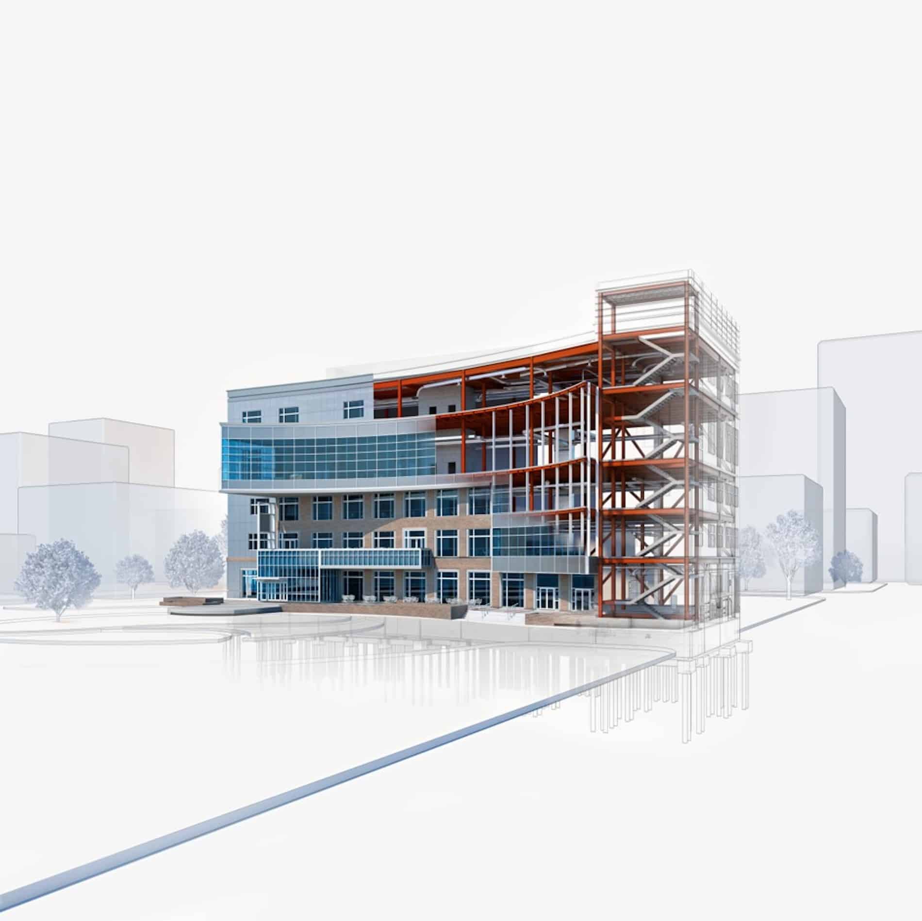
If everybody is so proficient with the change to a BIM process, then why aren’t building projects embracing it more widely? Why aren’t those firms who have embraced it finding the efficiencies that it promises? Why are our buildings not being constructed with less problems? Most importantly, why are those people who build those buildings still not convinced that the move to BIM has improved the quality, capability, efficiency and functionality of their products?
BIM has been around for over 15 years and still many architectural firms are struggling with how to actually leverage its potential. Engineering firms are not utilizing the information in the data-rich models being created. Contractors are spending valuable time remodeling the digital information created by their design teams so that they can utilize them for their purposes. Finally, these models are not of much use to the owners and even more work needs to be done for them to get a true digital repository of the structures they have created.
What has gone wrong? Why can we not create a true digital model of a building that can be used for design; then passed onto production of construction documents; then passed onto the contractor him/herself to build and extract useful data from; and finally passed to the owner to utilize throughout the building’s life-cycle. Along the way, why isn’t this data-rich model used for a myriad of additional benefits? A true building information model should exist throughout the life of a building.
The answer is that WE CAN! The secret is that all of these participants have to want to work together to achieve a set of common goals. The only person who can define what these are is the person paying the participants; yet that person does not have the experience or knowledge to do what is necessary. Until we can get together as one team pulling for that elusive set of common goals, the building process and the resulting building will be a disparate set of activities producing a result that reflects that lack of cohesiveness.
It is time that we got together and came up with a better way to use BIM so that everybody in the process can benefit.
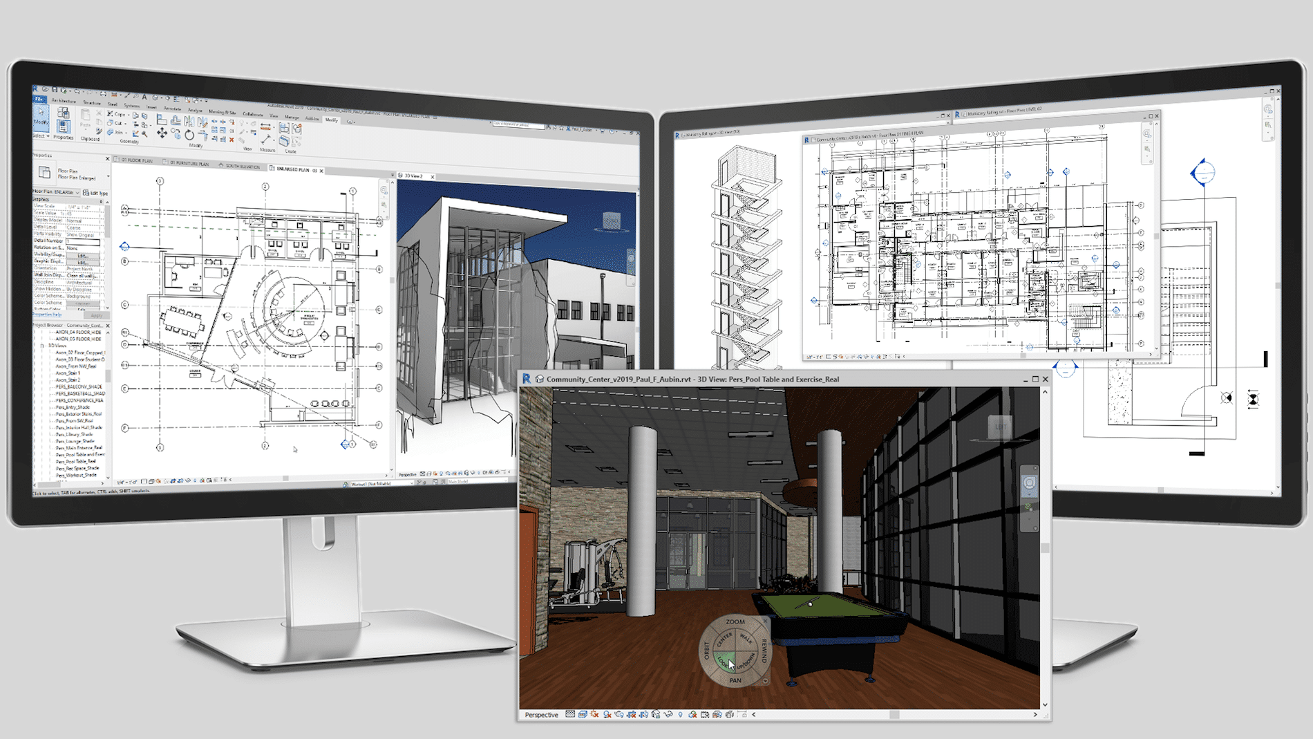
Getting started with Revit can feel daunting. It’s an unfamiliar program that may not work like your current software. But, like anything new as you become more familiar with it you will start to see the benefits of the basic modifying tools – Copy, Move, Align, Offset, Mirror, Array – as well as the special tools it offers like Systems, Analyze, and Collaborate all within a 3D environment. Layers, often an irritation, don’t even need to be thought about in Revit. Revit will place every object in the correct layer. You do not need to switch Ortho on/off or change Snaps. Revit will show alignment lines, angles, snap points on the go.If you are just starting out in Revit, here is some basics that you should know:
Model
Revit creates a virtual 3D representation of the model with the established relationships between elements.You can create as many views as required by the project. Every view of the model is a live view of the parametric elements. If an element is moved in one view, the position of that element in all of the views is instantly updated. Therefore, changing the elements will change the model instantly and all changes will be reflected on each view and plot sheets.
Model elements
All of the elements in Revit are Families and represent real objects. Families are grouped and sorted by category in the content libraries and in the Project Browser. The families, such as air terminals, plumbing fixtures, and mechanical equipment, are loaded into the template of the project or into the model from the Revit library or an external source. For example, from the manufacturer’s website or Autodesk Seek. All Families in Revit are parametric.
Instance and Type properties
Model elements in Revit represent physical instances in a model. When placed in a model they are visible in all views.
Type properties for the family are common for all types of the same family and contain information that applies to all instances of the same family type in the model. For example, type properties for an air terminal will be size – length x width. Changes made to type properties affect all instances of the family created from that type. Revit allows to change the family with a different type using the Type Selector. It is easy to create a new type within the family using the Duplicate function in the Type Properties dialog.
Instance properties contain information related to a specific placed instance of the family element in the model. For example, instance properties for an Air Terminal will be Air Flow. Changes made to instance properties affect only that instance of the family.
Annotation elements are also families that are used to add dimensions, notes, and tags to a view.
The first Revit project can be a frustrating one. You will be learning the program while you are working on your project. Even if you had some training, you’ll quickly find that not everything will work like it did in your training sessions in a real project. All the elements are drawn to real size and you need to be attentive to clashes while working on your model.
There are some little things you’ll want to remember:
Remember to place Air terminals or Electrical fixtures at the right elevation. Default for Air terminals is 0.000 and needs to be changed to match ceiling height. You also need to assign Flow to Air terminals.
As soon as you start a layout of the ductwork, Flow will be calculated through the system. You do not need to insert fittings working on ductwork or piping layout, Revit will do that for you.
Keep the section or 3D view of the area you are working on open. Don’t create sections just because you can; create one vertical and one horizontal, move them around as needed; create a new one when necessary and delete it once you are done.
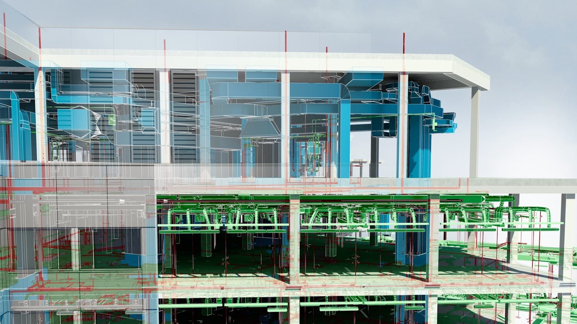
When you have placed MEP elements into a model, you can generate a duct or pipe layout manually, or Revit can generate it automatically from different layout solutions.
A parameter that defines the system is the Connector that is located within model elements and has pre-defined classifications within Revit. If you cross two ducts or two pipes with the same system classification on the same elevation, Revit will join those systems by creating a fitting. If this is not what you intended, place the systems on different elevations.
One Model element can have a number of different connectors with pre-set system classification, so elements can be assigned to a number of systems. A set of logically connected elements creates a system.
All components and systems can be seen in the System Browser – a tool that displays a hierarchical list of all system components in each discipline in the model.
Annotations are view-specific; they appear only in the view in which they were placed. Annotations can be copied from view to view, but any changes made to them in one view will not be transferred to any other views.
Now open Revit, select the System tool, drop some Air Terminals, place some ducts and now you can see the system you created in 3D. Wow! It looks impressive. But more impressive is the fact that you have not only created a system, and sized the ductwork with one click, you have also produced a section and a schedule which will be updated as you are working on the model. Revit has the ability to perform calculations such as pressure loss and static pressure, size ducts and pipes, and perform energy analysis on the design.
Contact us to find out more about Revit for MEP and how we can help you get the most from it.
Revit Model Groups are a wonderful thing when you know how to use them and follow some basic rules. They allow capturing repetition in the building model, and provide a way to tag through the groups, maintaining unique instance properties of the contained elements for scheduling.
This webinar will focus on the use of model groups for multi-unit residential projects.
During this webinar you’ll hear:
Best practices for creating and editing model groups.
How best to organize what goes in the group.
How to plan your project with groups to make it as efficient as possible.
Have a chance to ask a product expert your Model Group questions.
In this video you will learn some quick tips and the basics of organizing the schedules using the Browser Organization.
Revit 2018 provides various options for organizing the schedules in your project browser such as Filtering, Grouping / Sorting. It works in the same way as the regular views and you can group and organize using multiple choices or adding custom parameter.
Detail components are Revit families that can be placed in drafting views or detail views to add information to the model. They offer a more efficient, easier to use, and easier to control method of detailing than drawing individual detail lines.
This video looks at how to create your own detail components from scratch or by modifying out-of-the-box families so that they match your company’s standards.