• Canadian Flag Proudly Canadian Operated
  • The Digital Transformation Train is Leaving the Station, and We Should All Be on Board

    2020 has taught me a number of things, including presumably how indoor cats feel, that March and June are the same thing if you don’t go outside, and that if Godzilla were to stumble onto the shores of Tokyo tomorrow,  everyone would probably collectively shrug and go back to getting their coffee. While you’re probably thinking that none of these are very important lessons, I’d point out that a few of them are very strong evidence that today more than ever, is essential for businesses to better use available tools to automate processes, get employees connected, and develop strong digital connections with their customers. I’m not going to tell you which ones. Instead, we’ll jump to the point: the train probably left the station in March, but it’s not too late to get a ticket.

    If you’re not already on board, you’re missing out. Notably, this year has shown a prevalent increase in the “work from anywhere” culture. Covid and WFH are now BFFs, meaning this is a necessity for multiple reasons:  ensuring the safety of your employees, the risk of an outbreak impacting productivity in the workplace, and the added caveat that with the increase in WFH at many businesses means that your employees may see greener pastures elsewhere if you aren’t offering it.

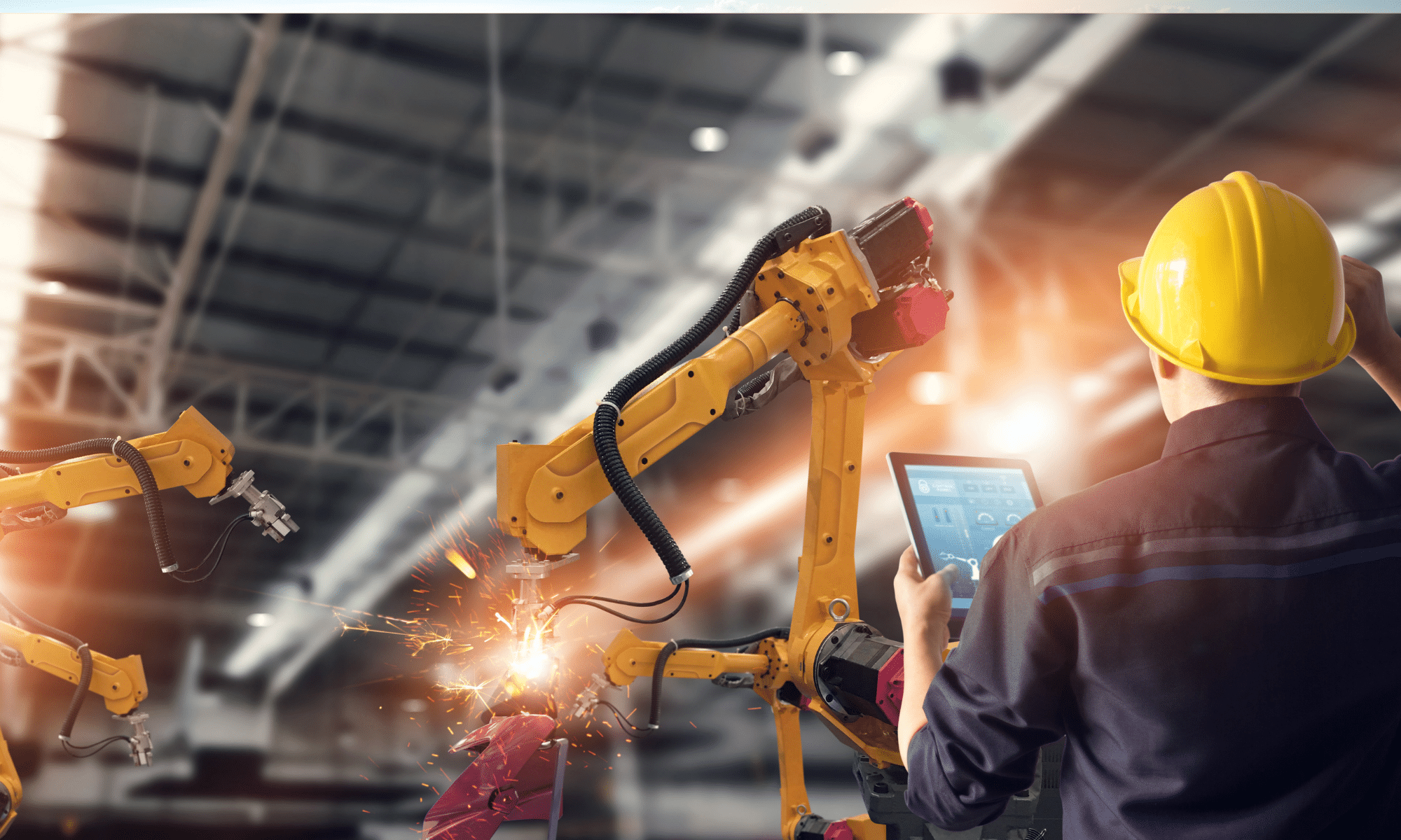
    This doesn’t mean that all digital transformation is created equal. Adopting Microsoft Teams and crossing your fingers is not an effective strategy for adapting to our new reality. Many workplaces have highly involved processes that require generous attention to detail and incredibly effective lines of communication.  So, for a manufacturing business, how do you ensure that this forced digital revolution doesn’t impact your team’s ability to be productive?

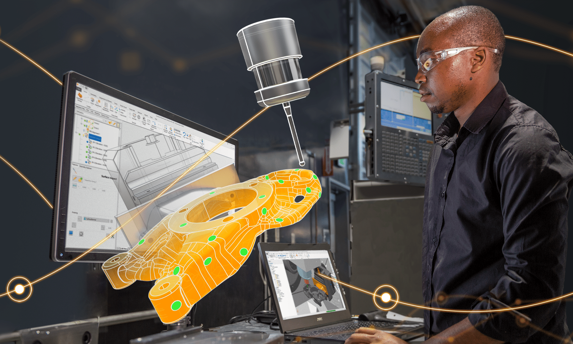
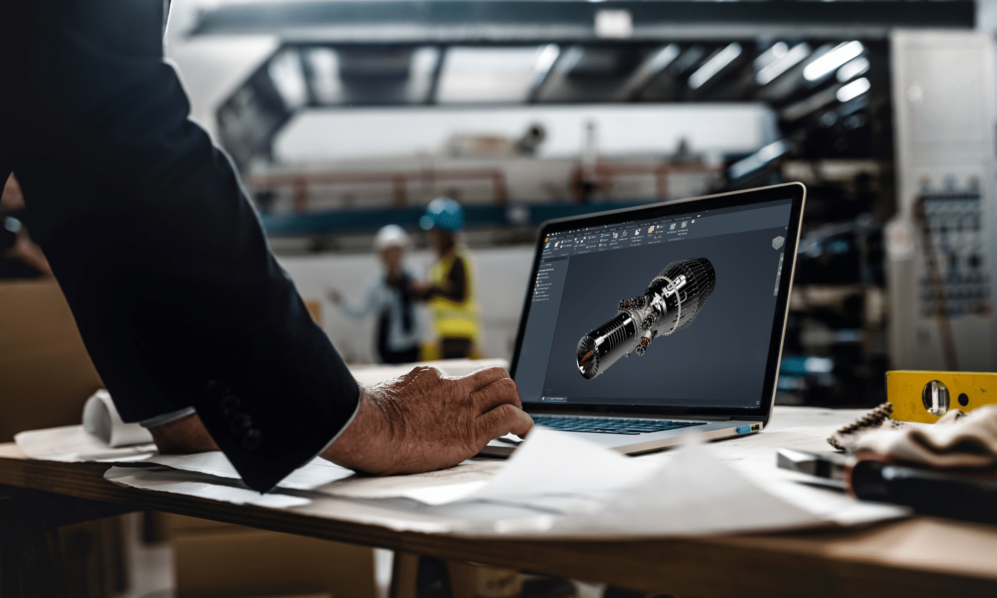
    Luckily, the revolution is no longer in its infancy, Covid has only helped it along. Many solutions already exist and for a manufacturer you can easily improve communication and visibility among your teams, automate workflows, and interface with your customer base. Autodesk Vault and Fusion Lifecycle are two such tools that, if not already in your workflow, should be up for consideration immediately.

    What is Vault and Fusion Lifecycle (FLC)? These two products are the rails that the digital transformation train rides on. Fusion Lifecycle is a product lifecycle management tool, and Vault is data management tool. Together, these products rule over your manufacturing data like Facebook does over the data of…well, everyone. With a single source of information, you can control and automate state change and change management tools, ensure a smooth process from project inception to engineering and manufacture easily than ever before.

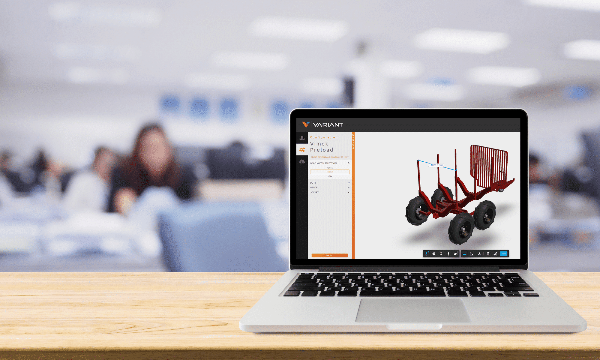
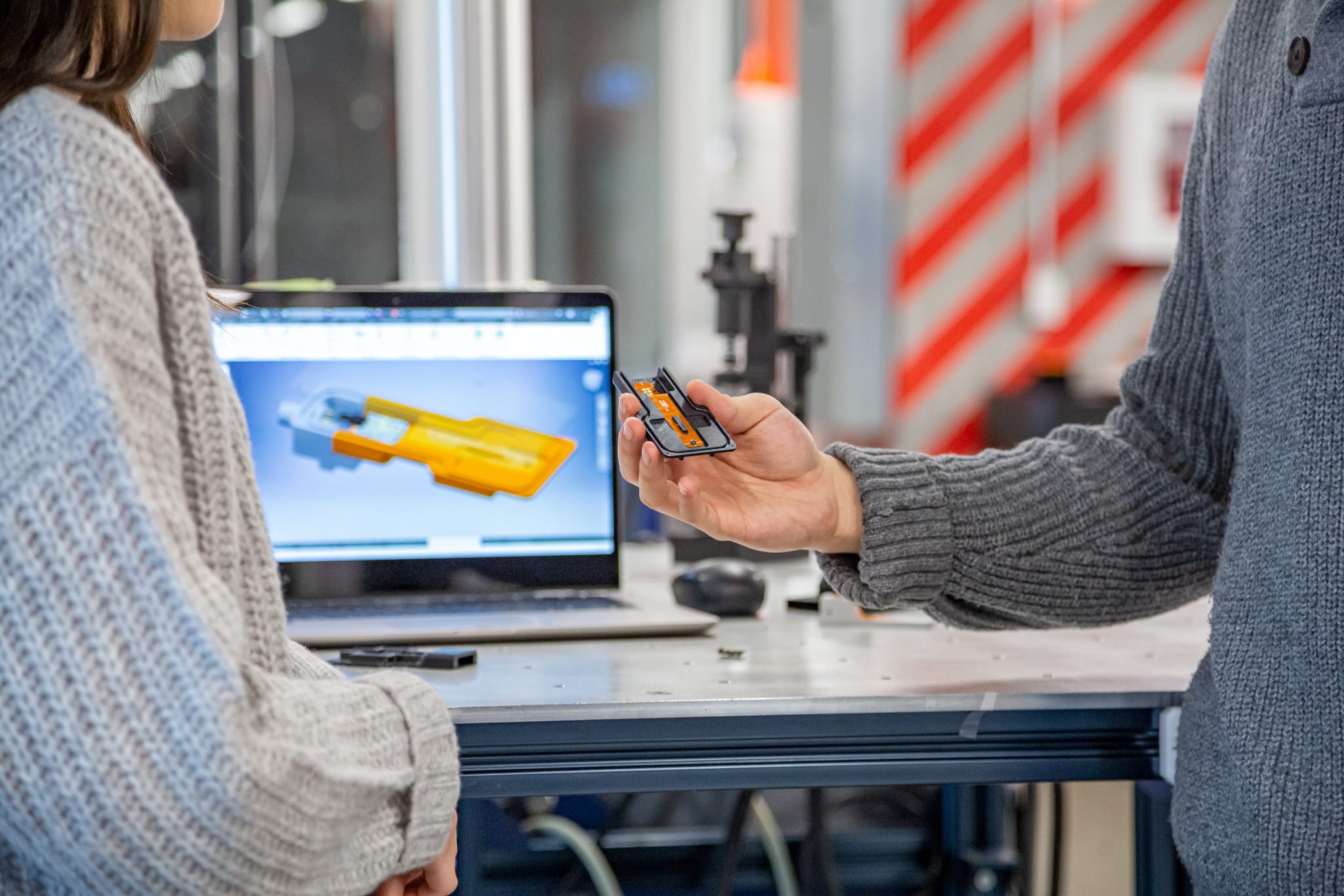
    The next tool you are most likely missing out on, is a sales tool to bring your CAD data to the fingertips of your sales reps and customers. Let your customers buy their tickets to ride. While some businesses may have leveraged Autodesk Configurator 360 in the past, moving forward, this tool will no longer be supported. This is why, we at SolidCAD, have developed Variant.  Variant is a web based iLogic configurator tool that can be used to easily convert Inventor iLogic assemblies into a powerful sales tool. Suddenly, that model that only engineering teams have seen becomes an interface that your customers can use to make selections, verify their choices, instantly obtain professional quotes, and order your products. If you still have massive catalogues with complex part numbers and PDF order sheets that often result in their own special type of chaos and deficiencies in your sales to manufacturing workflows, your children are probably already making fun of you on TikTok.

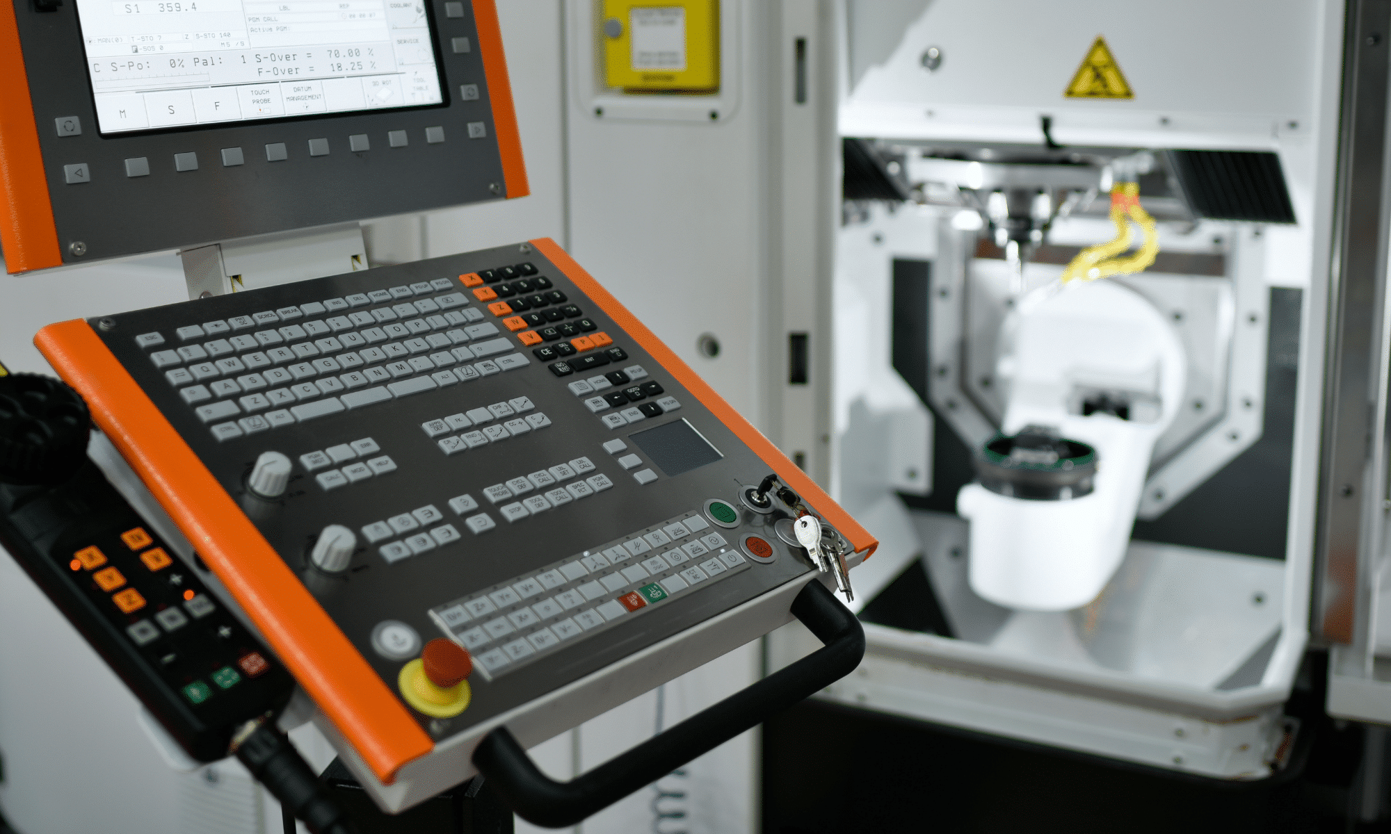
    Now, the buck doesn’t just stop here. Its no longer worth it to simply deploy these tools, pat yourself on the back for a job well done, and head home to binge a whole season of the Kardashians on your streaming platform of choice. A train that isn’t well designed likely won’t stay on the tracks for long. Variant, FLC and Vault are all highly customizable and can be fully integrated. A comprehensive digital transformation strategy includes ensuring that these products work perfectly in sync with the bespoke workflows and processes that your business wishes it could achieve, and in a way reduces manual data transfer and intervention wherever possible. Imagine freeing up the bandwidth your sales reps, engineers and production managers expend moving around all this data? Communicating these changes, reducing the possibility for human error and not to mention the likelihood of winning more bids as a direct result of the reduced sales cycle times are just a fraction of the possibilities.

    Not convinced? If your business isn’t already a passenger or ready to buy a ticket, take a moment to consider this: it’s highly improbable that you personally haven’t already benefitted from another business transforming a product, service, or industry. Whether you’ve been streaming Netflix to pass the time, connecting with family over Zoom, or watching your children use the internet to go to school, our lives have never been more touched by digital transformation.  If you have, then there is absolutely no doubt that the same applies to those who work for you or buy from you. In a time where leaving our homes can suddenly have a massive impact on our lives and those of our loved ones, every business needs to consider how they can embrace this era and bring customers and employees closer together while letting them remain well apart.

    All aboard!

    Autodesk Fusion 360 & Metallic Strip Animal Sculptures – Part 1

    Part 1

    I love sculptures and can spend hours at museums that devoted to sculpture. I also love structural Engineering and structural sculptures. Running into Artist Sung Hoon Kang‘s stunning animal sculptures that embody the movement, speed, and chaotic energy of the wind, fascinated me. You can take a look of his work here: Metallic Strip Animal Sculptures Radiate the Energetic Flow of Wind:  https://mymodernmet.com/kang-sung-hoon-sculptures/ Sung Hoon Kang‘s works got into in my head and made me think of how I can use Autodesk’s products such as Fusion 360 or 3DS Max to create/model these sculptures. I know Fusion 360 can combine organic shapes modelling, mechanical design, and manufacturing in one comprehensive package, but can it be used to create/model these kind of art works?

    The question stayed in my head until I found a possible solution by combining Fusion 360 and 3DS MAX. After finding the approach and workflow, I created the concept models of two metallic strip animal sculptures of a dog and a horse, and posted them on Fusion 360 Gallery. You can find and download my two metallic strip animal sculptures here:

    https://gallery.autodesk.com/projects/141060/fusion-360-for-art-work—-horse-metal-strips

    https://gallery.autodesk.com/projects/141004/fusion-360-for-art-work—dog-metal-strips

    Believe it or not, once you find a good workflow between 3DS MAX and Fusion 360, You can create these animal sculptures in 20 minutes or less.

    Here is how:

    Step 1Understanding Fusion 360 Freeform Tools

    You should know that Fusion 360 is not just an awesome freeform modeler; it is also a parametric modeler. Fusion T-Splines are a combination of NURBS and Subdivision modelling that was developed in 2003.The T-splines company was bought by Autodesk and was built into Autodesk’s Fusion 360. The T-Splines subdivision surface technology in the Freeform toolset make it easy to create completely smooth, curvature continuous, ‘Watertight’ NURBS surface models, that you can convert to Solid models.

    Fusion 360 Freeform tools are very helpful when you want to create an organic surface without having to spend lot of time planning and executing individual surface patches. T-spline surfaces are simple and intuitive, and it is really easy to iterate through a number of different options.

    Step 2Understanding 3DS MAX Polygon modeling

    Polygon modeling is more common with game design than any other modeling technique as the very specific control over individual polygons allows for extreme optimization. Usually, the modeler begins with one of the 3ds max primitives, and using such tools as bevel and extrude, adds detail to and refines the model.

    Fusion 360 loves Polygon modeling objects and it can quickly convert those objects into solids for you if needed.

    There are two kinds of mesh that you can import into Fusion 360; however, only mesh that came from Polygon objects can be converted to solids.

    To covert triangulated mesh to solid, it needs to be converted to Editable Poly before inserting into Fusion 360. These are the steps:

    • Import triangulated mesh into 3DS Max
    • Apply Subdivide (WSM) with “Display Subdivision” turn OFF
    • Use “Collapse To” to Collapse mesh
    • Turn Collapse mesh to Poly mesh
    • Apply “Quadrify All”.

    Step 3Understanding 3DS MAX Particle Flow

    Particle Flow is a versatile, powerful particle system for 3ds Max. It employs an event-driven model, using a special dialog called Particle View. In Particle View, you combine individual operators that describe particle properties such as shape, speed, direction, and rotation over a period of time into groups called events. Each operator provides a set of parameters, many of which you can animate to change particle behavior during the event. As the event transpires, Particle Flow continually evaluates each operator in the list and updates the particle system accordingly.

    Particle Flow provides several tools for determining where in the system particles currently reside, including the ability to change particle color and shape on an event-by-event basis. You can also easily enable and disable actions and events and determine the number of particles in each event. To speed up checking particle activity at different times during the animation, you can cache particle motion in memory. Using these tools, plus the ability to create custom actions with scripting, you can create particle systems of a level of sophistication previously unachievable.

    To create a Particle Flow, you need to place a PF Source and assign the PF source to an object. I used a dog model as an example to illustrate the use of PF source in this GIF image.

    Step 4Saving Particle Flow trails and Export them to AutoCAD

    You can make Particle Flow to generate animated Splines and save Particle trails. The animated Splines can be exported to AutoCAD format to be used for creating structural model or Poly mesh that will be turned into solids using Fusion 360.

    Step 5Creating Metallic strips from exported AutoCAD file

    The AutoCAD file can now be imported back into 3DS MAX. You can turn all the splines into Polymesh by simply turn on the ‘Enable in Viewport’ under Rendering option. In my example, I chose “Rectangular” option with Length =15mm and Width = 3mm

    At this stage, the model may require some modification for different strip thickness or clean up according to the artist’s design. Whenever you are ready, you can then export the entire MAX model out as a OBJ format to bring into Fusion 360 for fabrication.

    All Splines with rendering thickness property can now exported to OBJ format for Fusion 360 to convert to solids.

    Step 6Creating Metallic strips and complete the model in Fusion

    This step is very simple. There are various Insert commands you can use to insert other file formats. These options insert data into a current Fusion 360 design rather than opening the existing Mesh (STL or OBJ format), SVG, or DXF file. Refer to the following links for more information about inserting meshes, DXF, and SVG files into Fusion 360 designs: How to insert a mesh body into Fusion 360

    The next step is converting a mesh body to a b-rep or t-spline body in Fusion 360, the current limit for number of mesh elements is roughly 10,000. Meshes with greater than 10,000 elements will cause the performance of Fusion 360 to suffer and Fusion 360 may not be able to convert them to solid bodies.

    On my next blog, I will discuss and share with you some tips and tricks on how to convert mesh body to a b-rep or t-spline body in Fusion 360.

    You can also find me on AU 2020 by following this link and search for ‘Hung Nguyen’

    Until next time…

    SolidCAD releases new configuration product, Variant

    TORONTO, ON October 5, 2020 – Today, SolidCAD, Canada’s largest professional services company and Autodesk Platinum Partner, announces that they have developed and released their newest product, Variant. Variant is a web-based product configurator that is built on the Autodesk Forge platform and was developed for manufacturing customers that want to streamline their quotation and design-to-manufacturing processes. Just last week, SolidCAD announced that they became Autodesk’s newest Forge Certified System Integrator, and this week they are excited to publicly announce the availability of Variant.

    Variant goes well beyond Configure, Price, Quote (CPQ), where a user (whether it is a manufacturers internal sales team, a prospective customer or dealer) can make product selections almost anywhere with an intuitive web interface. The results include a 3D viewable model, associated bill of material and professional quotation.

    Variant is not only a product configuration tool but is also integrated into Autodesk Fusion Lifecycle PLM as well as Autodesk Vault, making the product a crucial part of an overall workflow. It not only provides sales quotations, but also offers the necessary information for downstream ordering and manufacturing.

    Customers that currently use Inventor’s iLogic feature or would benefit from doing so are excellent candidates for Variant as it enables them to provide those design variations to users on the web without the need of or knowledge of Inventor.

    Kevin Robinson, Sr. Business Strategy Manager at Autodesk added, “Design Automation is a powerful enabler for manufacturing customers, and we are excited to see how SolidCAD is extending the value of Autodesk Inventor designs containing iLogic with Forge. Variant looks like a fantastic cloud offering to help connect engineering to sales, and then to the end customer.”

    “Once again, SolidCAD is providing manufacturing companies with best in class tools” says Mark Gartner, National Director of Manufacturing at SolidCAD. “Many manufactures have aspirations of a product configurator and understand the benefits it will bring to their organization. Many have found that traditional CPQ products come up short, and most Engineer to Order (ETO) products are too expensive for the return on investment. This is the reason we developed Variant.”

    To learn more about this product, visit Variant at https://www.solidcad.ca/variant/ and register for SolidCAD’s upcoming Virtual Process Improvement event here: https://solidcad.swoogo.com/variant to get an understanding of the product firsthand. In addition, SolidCAD lead developer, Ryan Small and National Director of the Manufacturing division, Mark Gartner, will also be presenting Variant at this year’s Autodesk University digital conference on November 18-20: https://www.autodesk.com/autodesk-university/conference/schedule, just search for the session title “Sales Engineering Automation Using Forge, Fusion Lifecycle and Vault.”

    For more information, please contact:

    Mark Gartner, National Director of Manufacturing at SolidCAD
    587-414-1123
    mark.gartner@solidcad.ca

    SolidCAD is proud to announce themselves as an Autodesk Forge Certified System Integrator

    TORONTO, ON September 28, 2020 – SolidCAD, Canada’s largest Autodesk Platinum Partner and professional services company, is now an Autodesk Forge Certified Systems Integrator. Autodesk is a global leader in 3D design, engineering, and construction management software, providing software solutions that can improve industry workflows.

    Autodesk Forge is a cloud-based developer platform that can be used to visualize data, connect that data to external data sources for greater insight, automate tasks and connect teams and workflows.

    To earn this recognition, the SolidCAD team completed rigorous training with Autodesk experts, demonstrated a proven track record of helping multiple businesses build software integrations within existing systems and deployed custom, Forge-powered, cloud-based solutions.

    “SolidCAD is a valued Autodesk partner who for more than 25 years remains committed to our shared goal of continuous advancement to improve our customers’ success,” said Jim Quanci, Senior Director of Autodesk Forge. “Achieving status as an Autodesk Forge Certified System Integrator is a milestone for which SolidCAD should be proud and one we are confident will be welcomed across the industries we serve.”

    “We have a development team that is capable to support the entire range of Autodesk products and are excited to include Forge in our solution offering.” Ryan Small, National Director of Software Development at SolidCAD. “As our customers move to the cloud, SolidCAD is well-positioned to help them achieve their automation objectives and improve their overall workflow.”

    In addition, SolidCAD expects to release a new product on October 5, 2020 – a configuration tool built on the Forge system.[/gil_content]

    If you are interested in SolidCAD’s Forge services and want to learn more about future product updates, visit their profile on Autodesk’s site: https://forge.autodesk.com/systemsintegrators

    For more information contact:

    Ryan Small
    National Director of Software Development, SolidCAD
    Ryan.small@solidcad.ca
    1-877-438-2231 ext. 110

    SolidCAD’s acquisition of Fusiontek’s Bluebeam business unit

    Toronto, ON, August 24, 2020 – Today SolidCAD, a Bluebeam Platinum Partner, announced the acquisition of Fusiontek’s Bluebeam business unit. Located in Edmonton, Alberta, Fusiontek has operated as a professional services provider, delivering smart technology for the building design and construction industries. With years of experience, Fusiontek helps design and construction firms successfully implement BIM, Virtual Reality, and collaboration technology through their wide range of services including training, consulting and support. As Canada’s premier technology and professional service provider, SolidCAD is always looking for opportunities to grow and expand its presence in Western Canada and address the specific needs of the local AEC market.

    “We are very thrilled to welcome Fusiontek’s Bluebeam business unit to SolidCAD,” said Marcus Tateishi, President at SolidCAD. “Our team is ready to support and service their Bluebeam customers with the highest level of expert support, custom professional services, training and product expertise. We will ensure that this transition is both easy and effortless and is dedicated to ensuring that all clients’ Bluebeam needs are exceeded. On behalf of SolidCAD, we are happy to officially welcome our new customers to the family.”

    “We have chosen SolidCAD due to their strong commitment to customer service and national presence across Canada.” States Joe Magas, CEO of Fusiontek.  “We are happy to have our clients work with a partner that has an extensive team of over 30+ technical specialists with widespread experience in the architecture, engineering and construction industries. The SolidCAD team has proven to be a professional company that offers extensive services and support in both the official languages of Canada. We know that SolidCAD will continue to provide a high level of professionalism and support that we have offered to our customers for years.”

    About Fusiontek

    Since 2006 Fusiontek has helped AEC companies’ success with BIM, Virtual Reality and Collaboration solutions. We assist our clients to leverage the best technology for more efficient building design & construction. www.fusiontek.ca

    As of July 31, 2020 Steltman Tools are discontinued

    As of July 31, 2020, SolidCAD a Cansel Company has discontinued the sale of new subscriptions for Steltman Software, Steltman Tools. From this date and onward, new subscriptions, or renewals for maintenance plans to Steltman Tools will no longer be available for purchase.

    SolidCAD is committed to help improve our customers’ engineering design workflows. This decision will allow us to better partner with leaders in the Autodesk Developer Network market, such as CTC Software. SolidCAD and CTC will be delivering technologies that maximize productivity with custom applications and tools for Civil 3D. This collaboration strengthens our ability to enable more connected workflows and deliver high-quality services to optimize your workflow.

    For those located in the U.S, SolidCAD will continue to support you and your products for the remainder of the year until July 31, 2021, but during this time, you will be contacted by your new Account Manager from CTC Software to help you make the transition over.

    Book a meeting today to discuss your options

    Have Questions?

    We understand that this change might prompt questions, please review our FAQ to ensure you have all the necessary information.

    FAQ

    SolidCAD has made the difficult decision to discontinue Steltman Software, Steltman Tools as a product. With this decision, we intend to collaborate with other industry leaders who can better support your custom application and tool needs. As such, the current release of Steltman Tools ,2021, is the last release of that product.  Since that release, no updates or enhancements have been delivered and no new release versions are planned in the future.

    • Perpetual licenses do not expire and customers may choose to continue to use them after the expiry date of their maintenance contract.
    • No renewal or replacement licenses will be issued after the customers maintenance contract expires.
    • Perpetual network licenses do not expire and customers may choose to continue to use them after the expiry date of their maintenance contract.
    • No renewal or replacement licenses will be issued after the customers maintenance contract expires.

    SolidCAD has worked with CTC Software to enhance the capabilities of Civil 3D, and improve workflows historically supplemented by Steltman Tools. The modern but simple interface, installation, deployment, licensing and functionality of the CTC Software is improved over our previous offerings. We at SolidCAD are committed to bringing the best quality tools to you and your engineering/design teams. Our partnership with CTC Software, and the fantastic, proven offerings they have around Civil 3D are unmatched.

    Please contact your SolidCAD Account Manager so we can schedule a technical orientation of your use of Civil 3D, projects, and workflows and advise on the tools best suited ongoing for your firm.

    You may find that previous custom functionality you’ve had developed is included, or overlaps with existing features within the CTC Software CIM Project Suite, or CIM Manager Suite. They have been working for many years to solve many common shortcomings of Civil 3D. CTC’s development has been driven by customer feedback from day one many years ago, and will continue. SolidCAD would like to work with you to ensure existing features and functionality are fully leveraged within your firm to achieve the best project results possible

    Please contact your SolidCAD Account Manager so we can schedule a technical orientation of your use of Civil 3D, projects, and workflows and advise on the tools best suited ongoing for your firm.

    • If the customer needs to move an existing license to a new system prior to the expiry date of the customers renewal period a new perpetual license will be issued.
    • There will be no license renewals or replacement licenses after the customers current renewal period expires.

    Contact the SolidCAD support line at 1-877-438-2231 or Ramil Laxamana via 1-877-438-2231 ext. 238 or ramil.laxamana@solidcad.ca

    • We can help you with new Civil 3D workflows to accomplish what you need to achieve
    • New, similar, enhanced tools continue to be added to the CTC Civil Project Tools Suites
    • We do not support any specialty/custom tools previously created that are not in the standard Civil Essentials Tool set.
    • All Civil Essentials software and licensing support ends on July 31, 2021.
    To learn more about SolidCAD’s additional tools that can support your projects today, we encourage you to visit us at:  SolidCAD Products or visit CTC Software.

    The Multi Space Dimension of Autodesk Inventor

    Relativity says we live in four dimensions. String theory says it is 10. What are ‘dimensions’ and how do they affect reality?

    With three axes, we can describe forms in three-dimensional space. And Every point is uniquely identified by three coordinates. A Sphere can be described as:  x2 + y2 + z2 = 1.

    So, a sphere that sit in four-dimensional space can be legitimately described as:

    x2 + y2 + z2 + p2 = 1

    Our human brain can only receive and interpret a 3D world. When it comes to a 4, 5 or more dimension, our Engineering drafting become completely useless. Here are some examples I did with Inventor using its solid bodies Sweep feature:

    1. Colliding 3 dimensions to a common point, Inventor created an object that can be both sphere/cube. Is it a sphere or a cube?

    2.  Inventor can also be used to create a Hypercube frame in which our Engineering Standard CAN NOT present it on a drafting paper.

    These are 6 views of the same object, but why the 3 isometric views are completely different? Inventor showed that the shadow of 4D cube frame is the 3D cube.

    3.  Turn 3D cube frame into a 4D spiral ramp, we can see how De Vinci created a staircase that have the same entrance, but King, Queen, servants, and chauffeurs can never run into each other 😊

    4. My Klein Flower Vase is a 4D object of a 3D möbius loop.

    The log was inspired after watching this fantastic video:  Things to See and Hear in the Fourth Dimension. A great and simple mathematic lecture where it shows how four-dimensional shapes appear in a 3D world in a hands-on talk. Another great reading is this Radical dimensions

    What’s new in Inventor 2021

    Inventor 2021 comes with many visual changes that continue to modernize and streamline the 3d modeling experience. Several productivity enhancements and one fairly major AnyCAD update round out this year’s release and make it a valuable upgrade for users of any level.

    Here are some of the highlights;

    Dark Theme:

    The most notable visual update is the introduction of Inventor’s Dark Theme. This is available as a setting in the Application Options under the Colors Tab and follows the trend of many other applications as visual ergonomics becomes a more prevalent theme (so to speak!) among tech users. …Also; it also just looks better!

    It’s worth mentioning however, that they haven’t yet got around to making everything follow the Dark Theme. The Home Screen, file transaction, and project dialog boxes are a few examples of items that didn’t quite make it into this release, which is presumably why this is being tagged as “pre-release”. So one can only assume they’re still ticking away at all the different elements. Definitely a good start anyhow.

    Dock-able Property Panels:

    More commands have now been added to the list utilizing this new design first introduced in 2020. Along with Bend, Coil, Combine, Copy, Decal and a few others; Frame Generator and its associated end treatment commands now follow suit. Frequent FG users will likely need a few seconds to re-acquaint themselves with the new interface but once familiar, the streamlined workflow is sure to be a welcome change.

    As with the Dark Theme update, there are a few stragglers out there like the Fillet and Chamfer commands that will still have to wait their turn for a new look.

    File Naming Defaults:

    Mirror & Copy have now been added to the list, allowing users not only to control how these auto-generated files are named on creation, but also use attributes for their standard naming practices.
    As an added update to all three file naming default tabs, users can now manipulate the browser node to display as the filename or use a combination of the available attributes, allowing for some much needed control over the model browser organization.

    Frame Generator:

    In addition to the dialog box face-lift, Frame Generator has had another few minor but noteworthy updates such as:

    • A new Category filter in the dialog box allows the user to narrow down the available options by general shape, making profile selection much more efficient
    • When reusing a frame member users can now choose any previously reused member (rather than having to select the original source)
    • The Trim & Extend tool now supports using a curved face as termination
    • The Notch command now includes two additional custom profiles; Custom C and Custom T
    • Trim to Frame is now more appropriately named Corner Joint

    Revit AnyCAD:

    One of the most noteworthy updates for users who find themselves going back and forth between Revit and Inventor, is the interoperability between the two programs. Revit files can now be inserted associatively into an Inventor Assembly, maintaining a link to the native Revit data. This means changes made in Revit will now update in Inventor simply by clicking the update button.

    Drawing Workflow:

    When creating pre-configured sheet formats for standardized drawings, more options and functionality have been added to further reduce time spent downstream. You can now retain edge settings (ie. edge display) as well as check the “Fit views to sheet” option to automatically scale your views on creation. In addition, flat patterns in the sheet metal environment and parts lists for assemblies are now supported.
    As an added bonus for those of you who noticed it had disappeared; the Measure tool has made a comeback in 2021!

    The full details on these and all other 2021 updates can be found Here.

    The new Rotary machining strategy in Fusion 360 CAM is a thing of beauty!

    Last month, I wrote that a lot of improvements and new features had recently been built into Fusion CAM. One of these is the Rotary multi-axis 3D milling strategy, which has been a very long time in coming. What this is, is a strategy for mills or mill-turns that makes use of a rotary axis to 3D-machine around a part with a ball-nose cutter. The cutter is always kept pointed towards the center of rotation. Machining can be performed milling-style, with a back-and-forth toolpath along the axis of rotation and successive incremental steps (stepover) of the rotary. Better yet, machining can be performed turning-style, front-to-back (or top-to-bottom) with constant motion of the rotary and a specified stepdown per revolution. The centerline of the tool can be slightly offset (if your machine allows it) so as to stay off the center of the cutter.

    Well, I can say that the wait has paid off. We recently had a chance to put this new strategy through its paces with the help of our good friends at Dery’s Manufacturing of Regina using their big Nakamura WT-300’s mill-turns. The results were very impressive. We confirmed that using this strategy turning-style is particularly efficient, as it allows to take as big a depth-of-cut as needed and to potentially shape the part in a single pass.

    This new strategy clearly fills an important void. It will be appreciated in a variety of settings, including routers with a 4th axis mounted to the side. And it will be appreciated by users who have struggled in the past with “textured” or “3D” revolved parts, including STL models.

    Rotary is available as part of the “Manufacturing Extension” for Fusion 360, which includes other useful additions such as the very-powerful Steep-and-Shallow 3D strategy, borrowed from the all-mighty Powermill. The Manufacturing Extension costs 125 Cloud Credits ($125 USD) per month to access.

    Like many of the other recently-unveiled goodies, Rotary is unfortunately not available for Inventor CAM. That’s too bad since Rotary is an essential strategy that deserves to be included in the base offering of Fusion CAM, as well as in Inventor CAM and HSMWorks. I encourage you to vote for this on the Inventor IdeaStation. That being said, if you are an Inventor CAM user, your Product Design and Manufacturing Collection gives you access to Fusion. If you are an HSMWorks user, you as well now have free access to Fusion 360. And Autodesk has been working very hard of late to improve data exchange between Fusion and both Inventor and SolidWorks, in order to allow you to work with Fusion in parallel with these legacy platforms. Indeed, expect that later this year, Fusion will be able to retrieve CAM toolpaths saved inside an Inventor file.

    What’s new in turning? A lot!

    I mentioned in my last entry that Turning saw some important (and overdue) improvements of late. Indeed, you may have noticed that the Turning/Profiling function has been broken into a dedicated roughing strategy and a dedicated finishing strategy, for much more control and to allow for output of canned cycles. This happened around the middle of last year for Fusion, and a bit later for Inventor CAM.

    What you may not have noticed, however, is a myriad of small but very-welcome improvements everywhere else too. It’s a long list, and I refer you to Marti Deans’ excellent coverage here: https://www.autodesk.com/products/fusion-360/blog/turning-updates-fusion-360/

    Also, as I said in my last post, this is apparently just the tip of the iceberg. Turning experts have joined the Fusion development team and are hard at work implementing more functionality and innovative technologies (like Adaptive Turning). I hope to see a lot of the power of PartMaker ported to Fusion CAM!