• CTC & Feature Lines – Establishing the Hierarchy of Power!

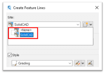
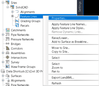
    Which option do you choose when creating a feature line? In my early days of learning Civil 3D I was given an analogy of buckets. That any of the objects in a site, “Bucket”, could not interact with other objects, this was the purpose of sites.

    This analogy was half-true and only the tip of the iceberg.

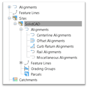
    For starters, sites can only house certain objects, and only parcels and grading groups are confined within sites.

    Alignments and feature lines have the option.

    The limited interaction between these “Buckets” only limits the interaction of the objects in a site from communicating with the objects in another site. That’s why we can choose to restrict feature lines and alignments.

    However, when feature lines are contained in a site, we have additional control over their interactions with one another.

    This is called Split Point Resolution and it allows us to set which feature lines govern at a crossing. Assigning styles to feature lines, we can set which styles are the most important for the design.

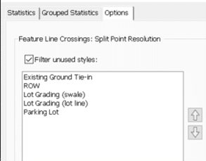
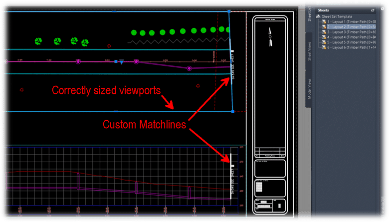
    I use this for lot grading to manage a variety of constraints and to make sure that right of way and existing elevations are respected.

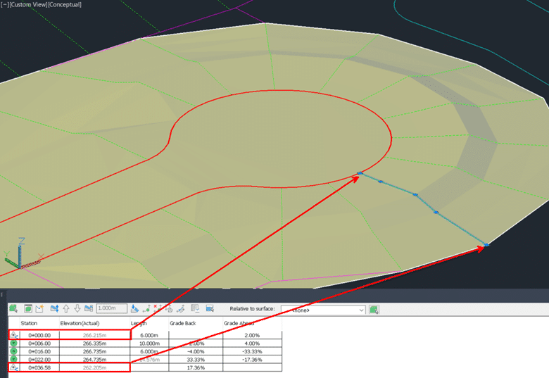
    Using the split point resolution while grading this cul-de-sac, it ensures the lot lines obey the right of way and the existing tie in points.

    This technique can be used in many other grading scenarios like drops in a curb or pond access paths.

    It is a powerful concept that not many designers have embraced yet.


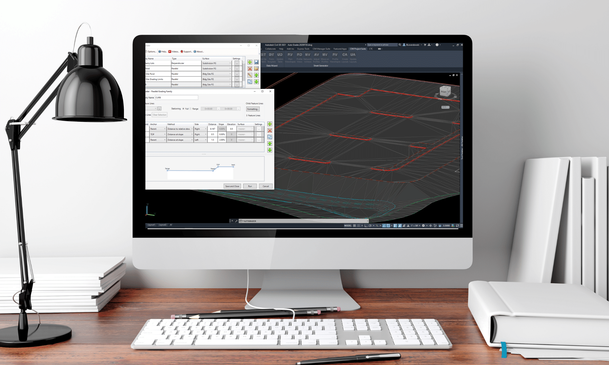
    And if that isn’t powerful enough for you, consider using CTC Software’s Auto Grader to automate the rest of your grading! This tool dovetails beautifully with the native split point resolution for feature lines in sites.

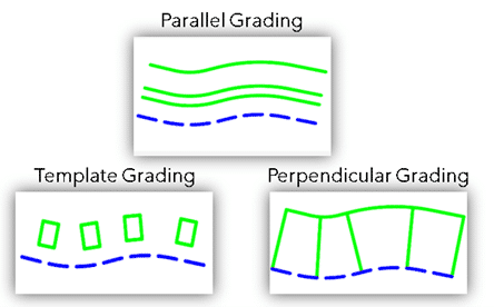
    Auto Grader has 3 different types of “Grading Families” that can be used to tackle almost any grading project.

    Parallel Grading allows mass dynamic stepped offsets from one or multiple baseline feature lines. Offering flexible grading for project areas such as curbs or ponds

    Perpendicular Grading allows mass insertion of elevation points/grade breaks across feature lines connecting to a baseline feature line. Offering automated grading solutions for lots in a subdivision or drop curbs.

    Template Grading is the newest addition to this tool allowing incredibly flexible 3D insertion control over template feature lines. Allowing you to establish grades from baseline feature lines and associate relative grades to the inserted template. This offers unparalleled flexibility for operations such as building envelope insertion.

    Hopefully, this challenges you to find even more efficiencies in your use of feature lines.

    Flexible, Customized Legends and QTOs with CTC’s Data Wizard.

    Flexible, Customized Legends and QTOs with CTC’s Data Wizard.


    How do you tackle quantity takeoffs in your projects? Do you use Civil 3D’s QTO Manager? Do you scale on paper or PDF’s?

    Between the inaccuracy of paper and PDF calculations, and the tedious setup and inflexibility of the MTO Manager, we don’t have a great solution for quantities of what’s in our projects.

    Data Wizard can make this cumbersome task a lot more efficient and accurate. This tool searches your drawing for Civil 3D & ACAD point, line, and area type objects then tabulates them all for you.


    This is a very versatile tool, and once objects are selected and filtered, we can choose specific data to extract. In the case of QTO, a layer description can be used to label the item. Then areas, lengths, and counts can be tabulated for each respective item.


    We can then sort and prep this data for AutoCAD Table insertion, or export to Excel. Data Wizard allows you to customize what you are looking for every step of the way!


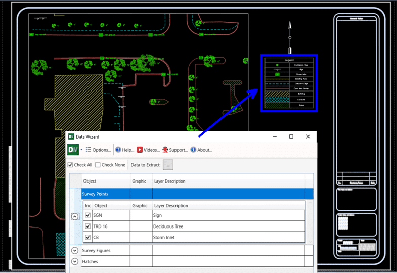
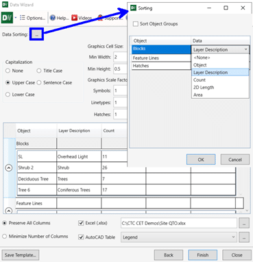
    Once the QTO is set up, we can also save the setup to a template to share among projects. This speeds up the QTO process even more for future projects.


    This is just one way to use Data Wizard. Alternatively, we can extract graphics and layer descriptions to produce sheet-specific legends for our plan production.


    This tool will save time and reduce human error with any tabulation tasks across your projects!

    Automated, Flexible, and Iterative Plan Production Tools. CTC’s Sheet Generator Workflow is the Whole Package.

    You can’t afford to create plan and profile sheets without these tools!

    If you have ever tried to create Plan & Profile sheets on mass with the Native View Frame tools it sure beats doing it by hand. But it also still requires a lot of manual manipulation after the layouts are created. And worst of all, you have to get it right the first time because the tools were not built to offer an iterative workflow.

    CIM Project Suite’s Sheet Generator workflow is a set of tools to speed up and increase the flexibility of the sheet creation process.

    Native View Frames vs. CTC Software’s Plan Viewshapes

    Plan Viewshapes consist of a block to represent the extent of your allowable viewport area in a sheet and a polygon to represent the actual shape and positioning of the viewport you would like to create. No more chopping View Frames at matchlines and hatching the rest of the rectangular area in your sheets.

    Creating profile views natively vs. with CTC’s CIM Project Suite.

    This is a bit of a trick comparison because the Sheet Generator workflow takes advantage of the native tools for creating profile views. Although, Sheet Generator offers much more mass editing controls for profile view heights, stationing, and object projection. These tools give you the ability to have uniformity across any number of profile views, and have lots of flexible options for centering these profile views on key information.

    The sheets that are created from CTC’s workflow will pull from company templates for sheet layout, and integrate into Sheet Sets seamlessly. The previously specified Plan Viewshapes and Profile Viewshapes create polygonal viewports with custom matchline blocks. The layout creation also adds north arrows, names layouts, and adds sheets to sheet sets automatically.

    The most important part of this workflow is that if the linear design changes in any way, all the sheets can be updated. Not recreated but updated! This means that custom notes and legends, details and blowups will all stay in the layouts. Updates to viewports, north arrows, stationing, matchlines, layout names, and sheet set information all take place automatically when the layouts need to incorporate a design change. This iterative flexibility is a game changer for large projects, it eliminating human error, and executing massive changes to sheets with just a few clicks.

    I hope the Sheet Generator workflow peaks your interest and helps you to find a new level of intuitive automation for your projects.

    CTC also has great tutorials for all their tools on their Youtube Channel.

    https://www.youtube.com/watch?v=_IlLnoK1qrk&list=PLTCH_HgPsbw_DWqEaVLF9xhWMjGPey9SI

    Finally, plan and profile sheets that update after design changes

    Plan production tools in Civil 3D are great for creating plan and profile sheets, but what about when the inevitable design changes come and you need to update your sheets? You either update them manually or recreate all new sheets. With CTC Software’s Sheet Generator, you can create plan and profile sheets that update after designs change, including refreshing of viewports, north arrows, matchlines, sheet names and numbers, sheet set data, and more. Sheet Generator provides better control on Profile Views, more flexible sheet management workflows, and easily dovetails with your company standards.

    For more click here