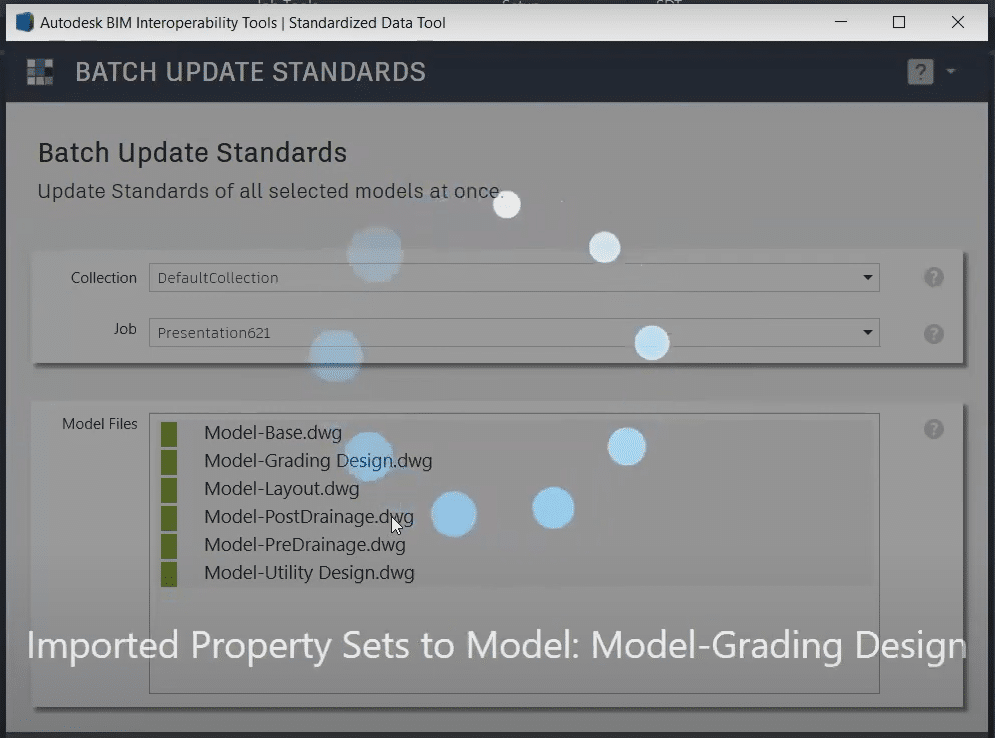
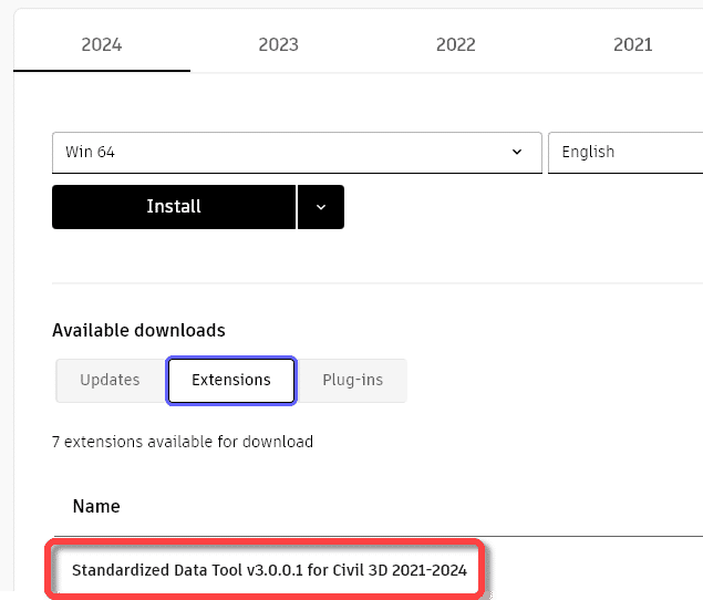
This free tool from Autodesk will allow you to quickly collect data from across all your Civil 3D drawing files and manage those data in a single Excel spreadsheet. It can be downloaded from your Autodesk site. It is available for Civil 3D versions 2021-2024. Here is its home page. To learn more, read on.
A few things to consider:
It’s all about metadata.
The new tool leverages the power of Civil 3D Property Sets exclusively.
Data across multiple drawings can be validated in a single operation.
Drawing objects can be queried. For example, from a selection of 12 drawings, list all pipes greater than 200mm diameter.
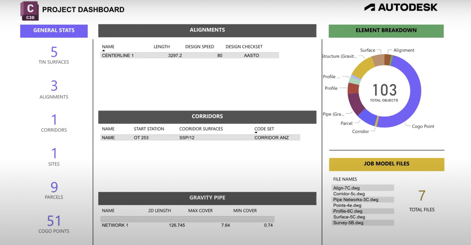
The project dashboard can be used to quickly summarize a project.
A simple migration path from legacy Innovyze products with InfoCare agreements to innovative, flexible Autodesk subscriptions.
From InfoCare to Autodesk Subscriptions
Beginning on May 7, 2023, Autodesk will be instituting the InfoCare to Subscription (I2S) program. The intention is to create an attractive, cost-effective way for customers to migrate from legacy Innovyze perpetually licensed products with InfoCare agreements or floating Innovyze subscriptions to more flexible Autodesk subscriptions with straightforward packaging – and all the convenient subscription administration tools offered with Autodesk subscriptions.
The InfoCare to Subscriptions (I2S) program enables you to move your Innovyze licensed products with InfoCare agreements or your Innovyze floating subscriptions to Autodesk subscriptions. With Autodesk’s diverse variety of product licenses and flexible agreements, we’re confident you can find the right tools and essentials for your unique business situation.
What does the I2S program mean for you?
On February 7, 2023, Autodesk ended multi-year renewals of InfoCare, and starting May 7, 2023, you can convert your licenses with InfoCare agreements or Innovyze floating subscriptions to Autodesk subscriptions at a discounted price.
We understand if have some questions regarding this adjustment. We hope to answer any queries you may have and give you all the information you need for a seamless transition. Check out this list of FAQs and our responses.
Autodesk offers a range of similar Innovyze subscriptions within the same product family. When trading in your licenses, you can purchase one discounted subscription for each fixed license traded in. For floating licenses and floating subscriptions, you may purchase two subscriptions for the price of one.
As always, if you are able, I recommend always installing the latest updates as they are released. There was a recent Civil 3D update, 2022.2.2, which provides a host of fixes. The 2023.2 update contains many of the same fixes.
One of the fixes was particularly notable to me as I’ve been working through a support issue with one of my customers. This fix completely resolves his issue.
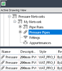
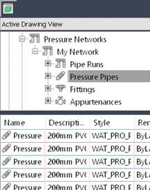
When I use Quick properties to select pressure pipes, fittings, and appurtenances, there are many.
Looking in the Prospector, however, there are few. Just 3 pipes and none of the other parts.
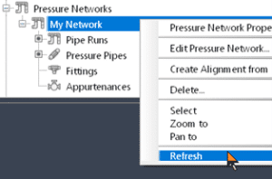
Where are they? With this new fix, I can Refresh the pressure network and all the parts return.
Are you “The One” who is master of label style creation for your firm? Have you seen this, and you don’t like it? If so, read on.
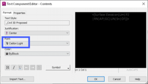
The code in question can occur if, within your Text Component Editor, you have font overrides.
There is a right click option that is supposed to remove any formatting. But you know what? Sometimes it doesn’t work. What to do?
The Solution:
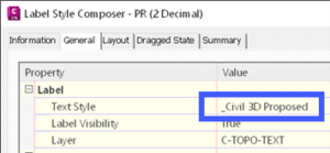
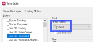
1. Ensure you don’t actually have an alternate font selected in the Format page. It needs to match the font specified in the Text Style for the label style. FYI, if you DO have an alternate font chosen, that {\fCalibri code will not go away with this technique.
2. Copy the “code” from the editor. Ctrl+A. Copy all of it!
3. Paste into Notepad.
4. Copy the same code, but from Notepad this time.
5. Paste back into the editor.
6. Done!
Yes, it does work. Why? I’m not sure. There must be some hidden creatures in there somewhere. Notepad does not allow such things to linger about.
To learn more about Civil 3D Label Styles and Fonts, or if you have any other questions, please feel free to contact us and one of our representatives will be in touch with you as soon as possible.
Do you use targets to modify the width of a lane or sidewalk? Would you like to vary a daylight slope over a station range? Are you looking for a different way to handle driveway curb letdowns? If you said yes to any of these, the 23.2 update for Civil 3D has a new feature that can help. Read on.
You probably know that geometry can be drawn, a polyline or alignment, and then defined as a target to change the width of a lane or sidewalk.
This works well, but there is a new option now. It’s called Corridor Transitions. Essentially, you can get the same result, but instead of drawing that geometry, the widths can be defined in a tabular format.
Select a corridor and choose Edit Corridor Transitions in the ribbon.
Enter values in the panorama that define the transition you need.
Click Apply.
Here, the width parameter of the LaneSuperelevationAOR is being controlled by the values in yellow. There are 3 stations ranges that define where and how the transition happens. Also, the DaylightMultiIntercept slope parameter is being controlled by the values in green. It transitions from a 2:1 slope to a 1:1 slope between 4+80 to 5+60, then there are 2 other transition regions after that.
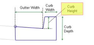
To define a driveway curb letdown, use the same procedure, except that the subassembly parameter that is varied would be the curb height. 3 transition regions will define a single letdown.
In this blogger’s opinion, this is one of the most complete mid-cycle updates in recent memory. Here are some highlights:
Performance
Always welcome!
Up to 60% Improvement During various operations including switching between drawings, corridor rebuild, and editing pipe networks.
Labels
Labels, especially when many exist in a Civil 3D drawing, can affect performance. All these settings are designed to boost performance.
Toggle labels on or off in Paper Space or Model Space If you don’t need to see labels right now, turn them off with a new setting.
Level of Detail on or off As you zoom out, labels will disappear.
Redraw options Choose when and how labels are redrawn.
Corridors
Users have been asking for this one for quite a while.
Transitions Use a tabular interface to define how subassemblies’ parameters transition between stations. For example, the daylight slope can be 2:1 at 0+000, transitioning to 4:1 at 0+050. Bus bays, or any lane widening can be defined this way. We are no longer limited to using polylines or alignments as width targets.
Profile Views
Display additional information about objects and their proximity to a parent alignment.
Point Proximity Band Show the distance between points and the alignment, and labels distances within the alert distance in red:
Alignment Proximity Band Show the distance between an alignment and the parent alignment and use ticks to show alignment segments within the alert distance:
Subassembly Composer
If you create your own subassemblies, these new features will benefit your productivity and help to reduce errors.
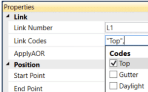
Point, Link, and Shape codes Define these codes in a dialog and apply them when and where needed.
Find and Replace Find and replace values almost anywhere in your code.
Dynamic Updates Change the source definition, and automatically update the instances.
Pressure Networks
Since Pipe runs, we continue to get useful features in this area.
Connect to Structures Pressure pipes can now be connect to pipe network structures and labeled.
Appurtenances Don’t Move These objects had the nasty habit of moving when the pipe run was edited. This is no longer the case.
Rail
These updates bring Civil 3D’s rail tool more in line with U.S. standards..
Turnout Blocks Turnout symbols can now be inserted perpendicular to the parent alignments.
Turnout Abbreviations Updated the abbreviation of critical points in the US turnout catalog in line with US regulations.
Project Explorer
Improve your reporting.
Property Set Objects Added support for reviewing property sets in the Project Explorer window.
Property Set Review Added support for including property sets in object sets, reports, AutoCAD tables, and spreadsheets.
Property Set Values You can determine the order and visibility of the value, description, and property names. Property set values can be edited.
Grading Optimization
Improve your preliminary grading.
Pathways Objects that represent sidewalks, driveways, and other ingress and egress paths.
Ridge Lines Objects that represent a linear elevation that directs drainage away from its placement.
Isolate Internal Zone Drainage You can now isolate drainage objects (drain lines, low points, and ridge lines) within a zone from affecting optimization outside of the zone boundaries.
Recreating a Civil 3D template from scratch is not something we look forward to, but it may be necessary at times. Read on to find out more.
You may ask why one would need to do this. Some users will do this when they upgrade to a new Civil 3D release. I have not seen any evidence that would convince me to do this. The only time I would recreate a template is if there is a serious problem that can’t be fixed without it. The recover command does a very good job at removing anomalies that may arise between Civil 3D releases.
So, you’ve decided to do it. What to do? There may be further steps that what you see below, but these will go a long way to making this arduous task a little more pleasant. The workflow below assumes that your original template is not completely pooched and can be successfully inserted into your new file.
1. Open problem template:
Export system variables to a file.
Note the assigned coordinate system in Civil 3D Settings, Files tab.
Use this CTC tool to export the Civil 3D Object Layers to a file. It is found in the CIM Manager Suite. Civil 3D’s Import Styles and Settings tool does a poor job of restoring these. If you don’t own CTC tools, enter Civil 3D Settings and note all the object layer settings so they can be restored in the new file.
Export any Layer Filters. If you’re using Civil 3D, this is easy.
Export any Layer States.
Export any Property Sets (if you are using Civil 3D).
2. Begin a new blank drawing using the acad,dwt or dwt files, and save the drawing.
3. Import system variables from the file you saved earlier. There are many settings saved in a DWG that must be restored.
4. Import the Layer Filters.
5. Import the Layer States.
6. Import the Property Sets and check any label styles where they are referenced to ensure they operate properly.
7. Insert problem file and explode. Purge anomalous blocks if necessary.
This step will insert most of the styles and any pre-configured objects like Point Grous, Surfaces, Pipe and Pressure Networks.
If the original file is too far gone, skip this step. You will need to recreate any pre-configured Prospector objects.
8. Set the coordinate system if there was one set in the original template.
9. Import styles and settings from problem file. If you skipped step 4, note that this command DOES NOT import everything. See this document for more information. These may need to be dragged and dropped form the original or recreated.
10. In the Prospector, inspect the names of any pre-configured objects and adjust if necessary.
11. Use this CTC tool to import object layers from the file you exported previously.
Restore them manually if you do not own CTC Tools.
12. Import paper space layouts from problem file.
13. Close the new file and run the RECOVER file to open it and check for problems.
14. Recreate the Scale List.
This can be easily done by creating some text in the original file and assigning all the scales to it. Copy this text and paste it into the new file then delete the text. New scales will now be available.
15. Test, test, test. To make sure everything works as it should.
16. Of course, make a backup of the original file and SAVE the new file with the original name.
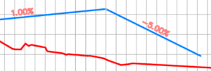
The goal in this example is to design the profile where each grade is an even number. It’s not as obvious as you might think. Thanks to my colleagues Dave Hill and Jae Kwon for pointing out the proper tool.
Read on to learn more…
Begin by modeling the first 2 segments. I’ll assume you know the best tools for this, but I’ll give you a hint. Use the Grid View; it’s your friend here.
To model the last 5% grade is not entirely obvious. Yes, a 5% tangent can be drawn from the end of the 1% grade, but it doesn’t end in the right place.
We sort of want to draw backwards from the end of the red profile then extend the 1% grade.
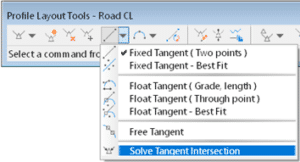
Use this tool and follow the prompts. First select the 1% grade, then pick Station and Elevation and the tie-in point. Then enter the grade, in this case -5% (the grade from the intersected PVI).
Label Genie, with it’s recent debut, changed how we do Civil 3D sheet annotation. Allowing automated insertion of labels across multiple drawings and layouts at once, Label Genie turns hours of work into minutes. The latest release will feature labeling in Profile and Section Views, and add many new label types, such as dimensions, blocks, pipe and pressure networks. Additional anchor objects will be included and new data sources will be available, such as block attributes, property sets, objects data, and more.
In this mini video series: Part 3, our Technical Consultant Infr/GIS – Colin Gaudet will showcase how you can automate labeling in Profile and Section Views, benefit from even more label types and anchor objects than before, and more.
For full information on CTC tools for Civil 3D click here
Auto Grader is a game-changer in Civil 3D site grading. Through dynamically linked feature line sets, users can create grading families for parking lots, ponds, subdivisions, and more. The latest release features a “template-based” grading method, allowing automatic insertion of a user-defined set of feature lines, such as a building pad, along defined baselines, such as a roadway. Other enhancements include more detailed surface targeting, automatic surface boundaries, better family preview controls, and other user-friendly features.
In this mini video series: Part 2, our Technical Consultant Infr/GIS – Colin Gaudet will showcase detailed surface targeting, automatic surface boundaries, better family preview controls, and other user-friendly features in the video below.
For full information on CTC tools for Civil 3D click here