fbpx
  • Civil 3D: Data Shortcuts – Do You Need Them?

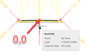
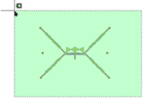
    Just to be clear, yes, we need to reference Civil 3D objects between drawings. There is no debate for many of my customers. To what I am referring are the little XML files that are created when you make a Civil 3D object available for sharing: A.K.A. creating a data shortcut. Those little XML files are not always required!

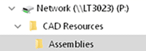
    Why am I brining this up now? Well, recently, a few of my customer are stressing out that they need to move projects to a new folder, or they need to archive projects, and they are wondering how things will unfold once they do.

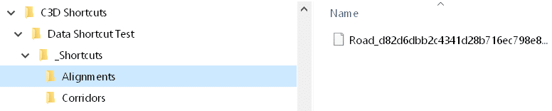
    What happens if those little XML files are deleted, moved, or otherwise go missing? Nothing! The path and file name are stored in the DWG file and the object is resolved without the need for those pesky XML files. Remember, it is a relative path to the source files. As long as drawings are moved relative to one another, all is well. If you move the source and host files to vastly different folders, then all bets are off.

    So then what are the XML shortcut files good for? They are used:

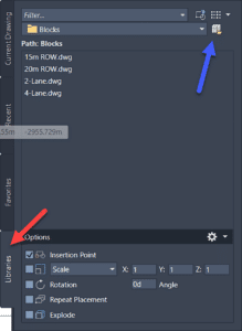
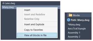
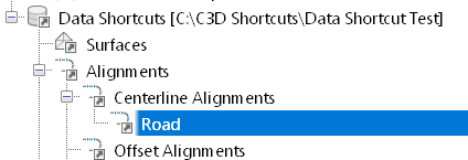
    • When creating data references from the Civil 3D Prospector. If you don’t have those XML files, you won’t see this. If the XML files have been deleted, simply open the source drawing and create new data shortcuts to reference additional objects,

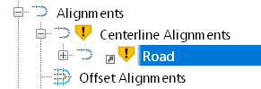
    • When moving Source and Host files to vastly different folders. The Data shortcut Editor can be used to repath multiple source files simultaneously. Fixing Broken References. Without those little XML files, you’ll have to repath all references individually.

    For any questions reach out to your sales rep or contact us at info@solidcad.ca

    Civil 3D: IFC 4.3

    There are many ways to send your data to colleagues, partners, friends, and enemies. DWG, LandXML, KMZ/KML, to name a few. They all have strengths and weaknesses. There’s a new(ish) kid on the block now. IFC. It has been around for a while now, especially in the building industry. It is emerging in the Civil Infrastructure industry, hence this article. Read on to find out more.

    I am going to preface this article by saying this is very new, there is not that much documentation about it, and I have limited practical experience. Ask me in 6 months and this may change. Please do your own research.

    What is IFC? Here is an article explaining it. Essentially, it is e vendor-neutral format used to exchange model data between software applications such as Civil 3D, OpenRoads, ArcGIS, and more. It is designed by a company named buildingSMART.

    Until recently, IFC has been for the most part ignored by Civil 3D users, mostly because it really wasn’t functional enough. Last year, buildingSMART released version 4.3 and this version allowed for more robust feature exchange. This year, with the released of Civil 3D 2024, Autodesk provides the tools to import, export, and configure IFC 4.3 format files.

    As a Civil 3D user, you must download and install the new extension. It can be found at manage.autodesk.com in Autodesk Access on your Windows desktop. IFC 4.3 does not come loaded with Civil 3D by default.

    What are the new commands? The release notes suggest that new commands are available in the Add-Ins ribbon tab in Civil 3D 2024. Maybe it didn’t work for me, or maybe I’m blind, but I do not see them. Most of the commands begin with IFCINF… Here is the online help document for more information.

    Is IFC like LandXML? The 2 formats currently do not share 100% parity. IFC does things that XML does not and vice versa. Your choice to use one or the other depends on your use case. Please, for your own sanity, experiment with them both to be certain your needs are met.

    One important thing to note is that IFC 4.3 files do not provide 100% round-trip functionality for all Civil 3D objects. Meaning, you can’t export your fancy parametric constraint rich alignment to IFC then import into another Civil 3D drawing and expect it to behave the same. These files are meant to be sent to non-Civil 3D users, surveyors, GIS specialists, etc.

    What about the future? Well, IFC 4.3, for all intents and purposes, version 1.0 for Civil 3D users. It is anyone’s guess how things will unfold.

    To learn more about Civil 3D, feel free to contact us.

    Civil 3D: Standardized Data Tool

    This free tool from Autodesk will allow you to quickly collect data from across all your Civil 3D drawing files and manage those data in a single Excel spreadsheet. It can be downloaded from your Autodesk site. It is available for Civil 3D versions 2021-2024. Here is its home page. To learn more, read on.

    Autodesk Civil 3D image

    A few things to consider:

    • It’s all about metadata.
    • The new tool leverages the power of Civil 3D Property Sets exclusively.
    • Data across multiple drawings can be validated in a single operation.
    • Drawing objects can be queried. For example, from a selection of 12 drawings, list all pipes greater than 200mm diameter.
    • The project dashboard can be used to quickly summarize a project.


    batch updateCivil 3d program

    Here is a YouTube playlist prepared by Autodesk.

    To learn more about Civil 3D, feel free to contact us.

    Civil 3D: Profile Grade Intersections

    The goal in this example is to design the profile where each grade is an even number.  It’s not as obvious as you might think.  Thanks to my colleagues Dave Hill and Jae Kwon for pointing out the proper tool.

    Read on to learn more…

    Begin by modelling the first 2 segments.  I’ll assume you know the best tools for this, but I’ll give you a hint.  Use the Grid View; it’s your friend here.


    To model the last 5% grade is not entirely obvious.  Yes, a 5% tangent can be drawn from the end of the 1% grade, but it doesn’t end in the right place.

    We sort of want to draw backwards from the end of the red profile and then extend the 1% grade.

    Use this tool and follow the prompts.  First select the 1% grade, then pick Station and Elevation and the tie-in point.  Then enter the grade, in this case -5% (the grade from the intersected PVI).


    C’est voilà.


    Civil 3D: Model Existing Underground Utilities Efficiently

    Civil 3D: Model Existing Underground Utilities Efficiently

    Must you draw existing gas, tel, and other similar underground utilities for your projects?  If you’re not using the technique described below, you’re using too much time!  Read on to find out more.

    Join us at Infrastructure University, session 3, on October 20th for more information about this technique. For now:

    Facts:

    1. For nearly every civil engineering project, we must identify existing features on our construction drawings so they may not be disturbed during construction and so we may design proposed works without conflicting with these existing features. They must appear in both plan and profile.
    2. It can take considerable time to draw and label them in the plan, and even more project them into profile.
    3. When there is an edit to the alignment, the profile locations must be recalculated, taking more time.
    4. Experiments have shown that it can take 84 seconds to draw each utility. Then 26 more seconds each when the alignment is edited.
    5. Using the technique described below, the time is reduced from 84 seconds to 20 seconds. But 0 seconds when the alignment is edited.
    6. For 160 utilities:
      1. 3.7 hours using the manual technique.                   69 minutes each time the alignment is edited.
      2. 53 minutes using the automated technique.         No extra time when the alignment is edited.

    Method

    1. Create pressure network parts lists, one for each utility. Assign styles accordingly.
    2. Create pressure networks, one for each utility. Assign the parts list and label styles accordingly.
    3. Model the existing utilities as pressure networks and project them into profile. The depth below ground can be automated.

    Grading Optimization Troubles and Fixes

    Grading Optimization was a great addition to the Civil 3D 2022 arsenal of tools. It is one of the first tools to incorporate AI into our civil designs and is able to help us get quick preliminary quantities, FG surfaces, and grading objects in a whole new way.

    Despite how exciting this is, there are some commonly encountered issues with getting started in GO.

    Civil 3D & GO 2022:

    One of the first issues I encountered with GO wasn’t apparent until I went to go design an assembly afterwards and got an error message. “Unable to execute the tool.” GO inhibited my access to toolpallets

    There has since been an Autodesk Knowledge Centre post created on this. And an update to GO as well as instructions in the link to the post below have offered an effective fix for this.

    The important thing to do if you are installing GO 2022 for the first time, is to make sure that Civil 3D 2022 has been installed and opened prior to installing GO 2022.

    *This issue will still occur if you install both at the same time without opening Civil 3D before installing GO.

    Click here to read Autodesk Knowledge Center post.

    This next problem is described in Matt Kolberg’s December 2021 post about the GO windows appearing, but only the shadow edge when you attempt to open the tool.

    To capture this fix in a few words, we need to add a new Windows environment variable to our system to enable us to use GO. This is a work around that Autodesk suggested, and a public fix will hopefully be pushed out for GO 2022 in the future.

    A link to Matt’s full explanation is below:

    https://www.solidcad.ca/civil-3d-grading-optimization-problem/

    Civil 3D & GO 2023:

    The above issues appear to be fixed in the 2023 version.

    The next issue worth exploring is that Grading Optimization requires more from your graphics card than Civil 3D. You may run into this blank warning screen below when opening GO, even though Civil 3D is functioning as expected.

    For me, this window popped up to block the screen with no way to close it when opening the Grading Objects Browser.

    There is no description in this dialog box, or posts on Autodesk Knowledge Centre, at the time I am writing this post, explaining the issue. This annoying window was due to an outdated graphics driver on my machine that didn’t affect Civil 3D.

    After updating the graphics driver, this window no longer appears.

    For any questions reach out to your sales rep or contact us at info@solidcad.ca

    Civil 3D Assemblies: Tool Palette or Block Library?

    Civil 3D Assemblies: Tool Palette or Block Library?

    Civil 3D comes shipped with pre-configured assemblies that may or nay not fit your needs.  We created another BLOG post here to show how to create your own and share them with others in your team.  There is another way…read on.

    The Cole’s notes are:

    • Make a new drawing.
    • Create your assembly in this new drawing placed at 0,0.
    • Insert that drawing into your design and explode the resulting block.

    In the linked article above, we suggested creating a tool palette.  This works well for blocks so they may be placed on the correct layers.  For assemblies, since this block will be exploded, this is not a requirement.  Might there be an easier way?  There is.  You see, tool palettes require a little maintenance.  The trick below does not.

    AutoCAD’s Block Library

    In Civil 3D 2022 or later, open the new block palette introduced in version 2020.  The option I’m about to illustrate is not available with 2020 or 2021.  You will see two things: a Library tab (red) and a button to select a folder (blue).  Clicking the folder button will prompt you to select a folder containing drawings.  If each of those drawings is an individual assembly, your job is done.  Drag and drop one of those into your drawing and ensure it is exploded.  You’ve just inserted an assembly.

    No maintenance is required.  Just save a new drawing with a new assembly into that folder and the next time AutoCAD is started, you’ll see the new content.  If you prefer to have all assembly blocks defined in a single drawing, that’s fine too, simply right click the drawing and choose…

    Enjoy!

    AutoCAD 2023: New Release

    AutoCAD 2023: New Release

    It’s that time of year; Autodesk has just released the 2023 version of their flagship drafting application, AutoCAD.  Read on to discover some of the new features.

    Click to peruse Autodesk documentation.

    Compatibility

    Likely one of the most common questions is about compatibility.  AutoCAD 2023 remains in the 2018 format.  There is no need to save files to previous versions unless your recipient is using 2017 or earlier.

    Markups

    I’m intrigued by this feature more than any other this year. PDF markups are ubiquitous in our industry, but there were few tools to help manage them.

    In AutoCAD 2023, PDF markups can be overlaid and displayed more easily, and they can then be imported as a trace layer and converted to AutoCAD objects. Markup assist will use text recognition to add AutoCAD text, multileaders, and revision clouds from the PDF markup. Image file formats are also supported if the PDF is scanned and marked with coloured pens.

    Insights

    Machine learning provides tips and tricks when and where you need them.  AutoCAD generates macro insights based on your unique command usage.

    LISP

    LISP apps can be loaded and run within the AutoCAD web app.

    General

    The command line is visible within each active floating window.

    Count has been updated to enable easier navigation and selection.

    The Sheet Set Manager has been given a performance boost and has a new interface in Autodesk Docs.

    ANNOSCALEZOOM controls mouse zooming in paper space.

    MTEXT objects can be converted to MultiLeaders.

    TRACE is now available on AutoCAD desktop, not just in the web app. You can contribute to other users’ traces.

    2D Graphics performance has been enhanced. Zoom and pan performance has been increased up to 50 times with many true type text objects, long polylines, and solid hatches. 

    The new TRAVERSALTHREAD system variable controls this.

    A new 3D graphics system (GSF) has been introduced and it promised to increase performance.  GSFENABLE is the new variable that controls this. It is ON by default. To experience the benefits of this, use the visual styles named Shaded or Shaded with Edges.  FASTSHADEMODE is a new variable that controls this behaviour.

    CUTBASE is a new command (Cut with base point found in the right-click menu) to allow the selection of a base point when cutting objects from a drawing.

    Add a new vertex to the end of a polyline with the extend vertex option

    Civil 3D: Sharing Assemblies

    Civil 3D: Sharing Assemblies

    So, you’re the technical team lead for your Civil Engineering firm, and you need to share amongst your team some Civil 3D Assemblies.
    You know how to create an AutoCAD tool palette, and you know that this is the best place to share assemblies – but you’ve tried, and it’s not working.

    If you’d like to learn how this is done read on.
    Palettes can be exported and then imported onto users’ machines, but when an assembly is edited, the creator must export again and then all the users must again import. This is not efficient.

    The Hard Way

    The method that Civil 3D uses to store assemblies on a palette works well, but to set it up is a bit of a bear.  Open this document to see the full details.  Here is a summary:

    • When an assembly is dragged to a tool palette a new DWG is created on your system. For my system this is:
      C:\ProgramData\Autodesk\C3D 2022\enu\Assemblies\Metric
    • You can create a tool palette with custom assemblies, sure, but you need to make these drawings available to your users. Usually, this means copying them to a network shared folder.
    • Even when you make them available, the DWG path must be defined in an ATC file that defines the palette, This is XML programming language and it can be difficult to find and disastrous if an error is made.

    The Easy Way

    I won’t say this is “The Best” method, but I believe it to be the easiest, quickest, and most foolproof method; and it’s the one I choose to use at this time.

    I won’t go into detail about how to perform each of these steps; it is assumed you know the technique. The short answer is that each assembly will reside in its own DWG file and that file will be stored in the shared network folder. That file will be a block in the tool palette.

    Open a drawing that conforms to your Civil 3D standards. Possibly one that already contains your desired assembly. 

    1. If the assembly has yet to be created, create it. 
    2. Ensure it is on the desired layer. Assign the desired code set style to it. Move it from its insertion point to 0,0. If this last step is skipped, the assembly will not be inserted properly later.


    3. Save the drawing to your shared network folder.


    4. WBLOCK and select the assembly and subassemblies together.  Ensure the insertion coordinates are 0,0,0 and provide the file name.  Click OK to create the drawing.


    5. Create a new tool palette or set current the destination palette for your new assemblies.  Drag the newly created drawing into the palette.

    6. To use the new assembly, drag it from the palette into a new drawing.  This will be a block, however.  It will need to be exploded once.

    7. You may suggest turning on the Explode option in the tool to avoid the explode step.  Indeed, I thought of that as well.  Problem is, this is what you get!


    That’s it.  Once the assemblies have been created, it takes about 45 seconds per assembly to add to the palette.  If edits are required, simply open the appropriate DWG, make the edits, and save.


    ArcGIS and AutoCAD – Free Background for everyone using AutoCAD

    Imagine a world where you could get high resolution background image maps to display and PRINT in AutoCAD.

    Esri and Autodesk are working closer than ever and this alliance benefits all CAD and GIS users. Esri provides a free ArcGIS for AutoCAD plugin. This plugin allows vanilla AutoCAD users to access Esri maps. As mentioned, the beauty of these maps is that they also print/plot in AutoCAD.

    I was surprised at the level of detail!

    Download ArcGIS for AutoCAD plugin for free at: https://www.esri.com/en-us/arcgis/products/arcgis-for-autocad

    Contact SolidCAD for more information about our newly created three-day  training course for any INFRA, GIS/FME training.