• Autodesk Fusion 360 & Metallic Strip Animal Sculptures – Part 1

    Part 1

    I love sculptures and can spend hours at museums that devoted to sculpture. I also love structural Engineering and structural sculptures. Running into Artist Sung Hoon Kang‘s stunning animal sculptures that embody the movement, speed, and chaotic energy of the wind, fascinated me. You can take a look of his work here: Metallic Strip Animal Sculptures Radiate the Energetic Flow of Wind:  https://mymodernmet.com/kang-sung-hoon-sculptures/ Sung Hoon Kang‘s works got into in my head and made me think of how I can use Autodesk’s products such as Fusion 360 or 3DS Max to create/model these sculptures. I know Fusion 360 can combine organic shapes modelling, mechanical design, and manufacturing in one comprehensive package, but can it be used to create/model these kind of art works?

    The question stayed in my head until I found a possible solution by combining Fusion 360 and 3DS MAX. After finding the approach and workflow, I created the concept models of two metallic strip animal sculptures of a dog and a horse, and posted them on Fusion 360 Gallery. You can find and download my two metallic strip animal sculptures here:

    https://gallery.autodesk.com/projects/141060/fusion-360-for-art-work—-horse-metal-strips

    https://gallery.autodesk.com/projects/141004/fusion-360-for-art-work—dog-metal-strips

    Believe it or not, once you find a good workflow between 3DS MAX and Fusion 360, You can create these animal sculptures in 20 minutes or less.

    Here is how:

    Step 1Understanding Fusion 360 Freeform Tools

    You should know that Fusion 360 is not just an awesome freeform modeler; it is also a parametric modeler. Fusion T-Splines are a combination of NURBS and Subdivision modelling that was developed in 2003.The T-splines company was bought by Autodesk and was built into Autodesk’s Fusion 360. The T-Splines subdivision surface technology in the Freeform toolset make it easy to create completely smooth, curvature continuous, ‘Watertight’ NURBS surface models, that you can convert to Solid models.

    Fusion 360 Freeform tools are very helpful when you want to create an organic surface without having to spend lot of time planning and executing individual surface patches. T-spline surfaces are simple and intuitive, and it is really easy to iterate through a number of different options.

    Step 2Understanding 3DS MAX Polygon modeling

    Polygon modeling is more common with game design than any other modeling technique as the very specific control over individual polygons allows for extreme optimization. Usually, the modeler begins with one of the 3ds max primitives, and using such tools as bevel and extrude, adds detail to and refines the model.

    Fusion 360 loves Polygon modeling objects and it can quickly convert those objects into solids for you if needed.

    There are two kinds of mesh that you can import into Fusion 360; however, only mesh that came from Polygon objects can be converted to solids.

    To covert triangulated mesh to solid, it needs to be converted to Editable Poly before inserting into Fusion 360. These are the steps:

    • Import triangulated mesh into 3DS Max
    • Apply Subdivide (WSM) with “Display Subdivision” turn OFF
    • Use “Collapse To” to Collapse mesh
    • Turn Collapse mesh to Poly mesh
    • Apply “Quadrify All”.

    Step 3Understanding 3DS MAX Particle Flow

    Particle Flow is a versatile, powerful particle system for 3ds Max. It employs an event-driven model, using a special dialog called Particle View. In Particle View, you combine individual operators that describe particle properties such as shape, speed, direction, and rotation over a period of time into groups called events. Each operator provides a set of parameters, many of which you can animate to change particle behavior during the event. As the event transpires, Particle Flow continually evaluates each operator in the list and updates the particle system accordingly.

    Particle Flow provides several tools for determining where in the system particles currently reside, including the ability to change particle color and shape on an event-by-event basis. You can also easily enable and disable actions and events and determine the number of particles in each event. To speed up checking particle activity at different times during the animation, you can cache particle motion in memory. Using these tools, plus the ability to create custom actions with scripting, you can create particle systems of a level of sophistication previously unachievable.

    To create a Particle Flow, you need to place a PF Source and assign the PF source to an object. I used a dog model as an example to illustrate the use of PF source in this GIF image.

    Step 4Saving Particle Flow trails and Export them to AutoCAD

    You can make Particle Flow to generate animated Splines and save Particle trails. The animated Splines can be exported to AutoCAD format to be used for creating structural model or Poly mesh that will be turned into solids using Fusion 360.

    Step 5Creating Metallic strips from exported AutoCAD file

    The AutoCAD file can now be imported back into 3DS MAX. You can turn all the splines into Polymesh by simply turn on the ‘Enable in Viewport’ under Rendering option. In my example, I chose “Rectangular” option with Length =15mm and Width = 3mm

    At this stage, the model may require some modification for different strip thickness or clean up according to the artist’s design. Whenever you are ready, you can then export the entire MAX model out as a OBJ format to bring into Fusion 360 for fabrication.

    All Splines with rendering thickness property can now exported to OBJ format for Fusion 360 to convert to solids.

    Step 6Creating Metallic strips and complete the model in Fusion

    This step is very simple. There are various Insert commands you can use to insert other file formats. These options insert data into a current Fusion 360 design rather than opening the existing Mesh (STL or OBJ format), SVG, or DXF file. Refer to the following links for more information about inserting meshes, DXF, and SVG files into Fusion 360 designs: How to insert a mesh body into Fusion 360

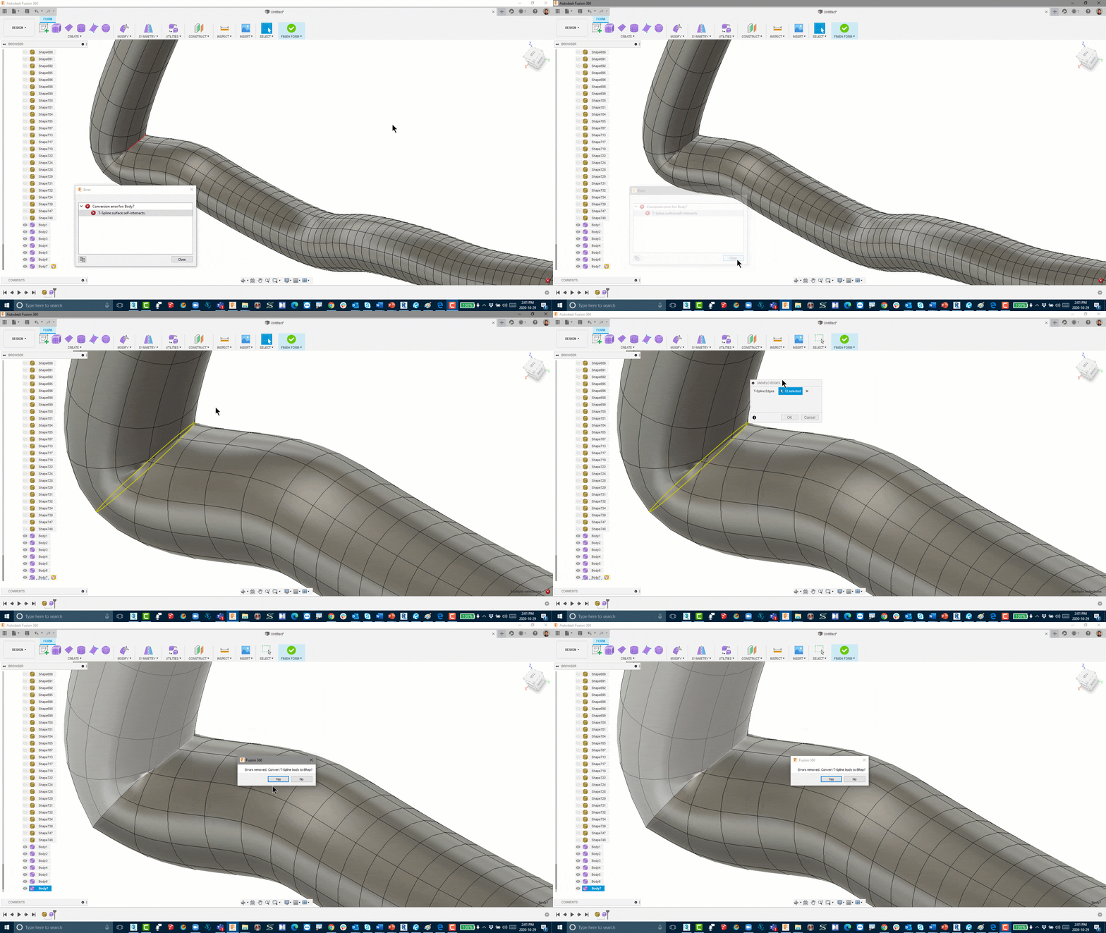
    The next step is converting a mesh body to a b-rep or t-spline body in Fusion 360, the current limit for number of mesh elements is roughly 10,000. Meshes with greater than 10,000 elements will cause the performance of Fusion 360 to suffer and Fusion 360 may not be able to convert them to solid bodies.

    On my next blog, I will discuss and share with you some tips and tricks on how to convert mesh body to a b-rep or t-spline body in Fusion 360.

    You can also find me on AU 2020 by following this link and search for ‘Hung Nguyen’

    Until next time…

    Plumbing Code Calculations With Spreadsheet Link and Schedule XL – Part 1

    Posted from CTC BIM Project Suite White Paper Library –  CTC Software

    The Issue

    Revit® has trouble with complex calculations and the ability to run cross-category math. This can be frustrating when design calculations need to be run. In the case of plumbing code calculations, we need to take the occupancy of a defined area (floor, smoke compartment, etc.) and use these totals to derive the number of different plumbing fixtures that are required by code to be designed into these areas. Many firms run these calculations manually, but this can be done far more efficiently. This white paper will describe how a re-usable workflow can generate occupancy, calculate plumbing fixture counts and generate graphics for use in Revit to present this information in a live model.

    Typical Workflow

    In manual workflows, some Architectural firms will use either fake calculated values in a Revit schedule, then sometimes copy those values across to a real parameter for display in a tag, a schedule, and on the actual room object. Some firms may also use a calculated value in a tag to reduce some of the manual data transfer. Other firms will export schedules to Excel®, and run calculations there, but then must manually copy the values back into Revit. In all cases, the process is very manual and extremely error prone.

    This is also rather time consuming, reducing potential production time. Regardless of how we get the room occupancy, we always must manually transfer the occupancy to a spreadsheet for our code checks, present the information in a meaningful way and return this information back to Revit. This is also entirely manual and error prone. Nothing keeps this information up to date with the Revit project model. There needs to be a better, more efficient way to do these types of calculations, and return the result of our efforts to the Revit project model and include the information on the construction document set.

    Solution

    This entire workflow can be heavily automated using the Spreadsheet Link and Schedule XL tools from the CTC BIM Project Suite. Your current spreadsheet can be incorporated, and the values entered far more automatically. Even the room occupancy calculations can be tuned to your liking, entered directly into the room/area/space elements you are using in the Revit model. Further, the spreadsheet graphics can be directly linked into the model, avoiding any manual image or CAD file workflows.

    • Establish predictable, repeatable workflows for all Revit users
    • Leverage existing spreadsheet layouts so formatting in Revit aligns with company graphic standards
    • Implement the power of spreadsheet formulas to drive calculations and graphics
    • Import spreadsheet graphics directly into the Revit model for use on sheets

    SolidCAD releases new configuration product, Variant

    TORONTO, ON October 5, 2020 – Today, SolidCAD, Canada’s largest professional services company and Autodesk Platinum Partner, announces that they have developed and released their newest product, Variant. Variant is a web-based product configurator that is built on the Autodesk Forge platform and was developed for manufacturing customers that want to streamline their quotation and design-to-manufacturing processes. Just last week, SolidCAD announced that they became Autodesk’s newest Forge Certified System Integrator, and this week they are excited to publicly announce the availability of Variant.

    Variant goes well beyond Configure, Price, Quote (CPQ), where a user (whether it is a manufacturers internal sales team, a prospective customer or dealer) can make product selections almost anywhere with an intuitive web interface. The results include a 3D viewable model, associated bill of material and professional quotation.

    Variant is not only a product configuration tool but is also integrated into Autodesk Fusion Lifecycle PLM as well as Autodesk Vault, making the product a crucial part of an overall workflow. It not only provides sales quotations, but also offers the necessary information for downstream ordering and manufacturing.

    Customers that currently use Inventor’s iLogic feature or would benefit from doing so are excellent candidates for Variant as it enables them to provide those design variations to users on the web without the need of or knowledge of Inventor.

    Kevin Robinson, Sr. Business Strategy Manager at Autodesk added, “Design Automation is a powerful enabler for manufacturing customers, and we are excited to see how SolidCAD is extending the value of Autodesk Inventor designs containing iLogic with Forge. Variant looks like a fantastic cloud offering to help connect engineering to sales, and then to the end customer.”

    “Once again, SolidCAD is providing manufacturing companies with best in class tools” says Mark Gartner, National Director of Manufacturing at SolidCAD. “Many manufactures have aspirations of a product configurator and understand the benefits it will bring to their organization. Many have found that traditional CPQ products come up short, and most Engineer to Order (ETO) products are too expensive for the return on investment. This is the reason we developed Variant.”

    To learn more about this product, visit Variant at https://www.solidcad.ca/variant/ and register for SolidCAD’s upcoming Virtual Process Improvement event here: https://solidcad.swoogo.com/variant to get an understanding of the product firsthand. In addition, SolidCAD lead developer, Ryan Small and National Director of the Manufacturing division, Mark Gartner, will also be presenting Variant at this year’s Autodesk University digital conference on November 18-20: https://www.autodesk.com/autodesk-university/conference/schedule, just search for the session title “Sales Engineering Automation Using Forge, Fusion Lifecycle and Vault.”

    For more information, please contact:

    Mark Gartner, National Director of Manufacturing at SolidCAD
    587-414-1123
    mark.gartner@solidcad.ca

    SolidCAD is proud to announce themselves as an Autodesk Forge Certified System Integrator

    TORONTO, ON September 28, 2020 – SolidCAD, Canada’s largest Autodesk Platinum Partner and professional services company, is now an Autodesk Forge Certified Systems Integrator. Autodesk is a global leader in 3D design, engineering, and construction management software, providing software solutions that can improve industry workflows.

    Autodesk Forge is a cloud-based developer platform that can be used to visualize data, connect that data to external data sources for greater insight, automate tasks and connect teams and workflows.

    To earn this recognition, the SolidCAD team completed rigorous training with Autodesk experts, demonstrated a proven track record of helping multiple businesses build software integrations within existing systems and deployed custom, Forge-powered, cloud-based solutions.

    “SolidCAD is a valued Autodesk partner who for more than 25 years remains committed to our shared goal of continuous advancement to improve our customers’ success,” said Jim Quanci, Senior Director of Autodesk Forge. “Achieving status as an Autodesk Forge Certified System Integrator is a milestone for which SolidCAD should be proud and one we are confident will be welcomed across the industries we serve.”

    “We have a development team that is capable to support the entire range of Autodesk products and are excited to include Forge in our solution offering.” Ryan Small, National Director of Software Development at SolidCAD. “As our customers move to the cloud, SolidCAD is well-positioned to help them achieve their automation objectives and improve their overall workflow.”

    In addition, SolidCAD expects to release a new product on October 5, 2020 – a configuration tool built on the Forge system.[/gil_content]

    If you are interested in SolidCAD’s Forge services and want to learn more about future product updates, visit their profile on Autodesk’s site: https://forge.autodesk.com/systemsintegrators

    For more information contact:

    Ryan Small
    National Director of Software Development, SolidCAD
    Ryan.small@solidcad.ca
    1-877-438-2231 ext. 110

    Five Ways to Design and Access Masterfully Efficient Digital Dashboards in Revu

    This article was originally published by Bluebeam, Inc. on the Bluebeam Blog.


    Digital dashboards offer teams a centralized, easily navigable hub for critical project documents and information. Don’t create one without making these considerations

    Construction projects are loaded with complexity. Hundreds—sometimes thousands—of documents are assembled and distributed to scattered teams on frenzied jobsites, where dozens of subcontractors are hard at work building off carefully detailed plans. 

    Time is money in construction, which means clear, accurate and expedient transfer of information is paramount to a project’s success. Aside from the hordes of design plans (many now digital) construction workers need to efficiently complete their work, there are several additional resources that they need at their disposal, most of which live on the internet or in other cloud-based tools.  

    Thankfully, the evolution of construction technology, digital transformation and collaboration have made accessing and organizing this information more convenient. Bluebeam Revu is one of the tools that has grown to help construction, engineering and architecture workers in this area. 

    Revu allows users to create customized digital dashboards for their project teams so that all relevant construction documents and supplemental reference information can be neatly organized and accessed through Studio Projects—regardless of whether team members are in the field or in an office. 

    “The whole point of a digital dashboard is to eliminate that file hierarchy of folders and eliminate the time spent looking for files,” said Lillian Magallanes, Bluebeam’s industry alliances manager, who has extensive experience creating digital dashboards.  

    Building digital dashboards in Revu and providing collaborators access via Studio Projects can be as simple as hyperlinking to a few of a project’s most-relevant design documents or as comprehensive as outfitting an intricate web of links using JavaScript to create a one-of-a-kind branded experience. The final product can be used not just by project teams during construction but also by owners and facilities managers throughout the building’s lifecycle.   

    Here are four considerations to keep in mind as users build out digital project dashboards: 

    Start with the end in mind 

    What type of worker will be using the dashboard to retrieve information? 

    Will they be architects or engineers in an office on a desktop computer or laptop? Or will they be field superintendents or subcontractors needing to track down a design spec in the middle of a hot, blistering day on a jobsite?  

    What’s more, aside from the user’s environment, what frame of mind might they be in when looking for the information linked in a digital dashboard? 

    Starting with this end in mind, according to Magallanes, is essential before starting to assemble a digital dashboard in Revu. “The last thing most people involved in a construction project want to do is have to learn something new that is complex just so they can find a file and send it to someone else,” Magallanes said.  

    Map out information and navigation 

    Once the frame of the end-user’s mind has been determined, then it’s time to map out the navigation of where the different hyperlinked buttons and elements of a dashboard will lead. Simple dashboards may only include a handful of buttons leading to the most relevant design documents.  

    More comprehensive digital dashboards, however, may involve a few different layers of navigation that allow users to find and access disparate pieces of information for a project in a few quick clicks, while also linking to tools and resources either found on the web or as part of other cloud-based digital applications.   

    “This is really going to help someone think what levels of information need to be brought up,” Magallanes said.  

    Understanding how information is presented—as well as the user experience of navigating through it—is essential when building an effective digital dashboard.  

    Bolster collaborator access with Studio Projects  

    Creating a simple-to-use project dashboard is only half of what makes it so valuable. The other half is ensuring that the people using it can access it easily and efficiently. 

    This is where Studio Projects, a document management capability in Revu, comes in. After creating and configuring a detailed dashboard in Revu, the most efficient way to make the most out of it is to host it for both internal and external collaborators with ease through Studio Projects 

    Hosting a project dashboard in Studio allows teams to access corresponding documents from the dashboard without having to leave the Studio environment. This makes accessing often-viewed documents faster since those documents are not hosted in a company’s protected server or other cloud-storage service but in a shared Studio Project.  

    Consider making design a priority  

    Some projects may see a digital dashboard as a simple, easy-to-access portal for a few significant project contributors on a jobsite. Others, meanwhile, may decide to build something expansive for a large build where dozens and dozens of subcontractors are using the tool, oftentimes jumping in at the mid-point of a project.  

    Still, for some general contractors, creating a comprehensive digital dashboard is an opportunity to create a branded experience—not just for the subcontractors collaborating on the project, but the building’s owners and facilities managers after the building is fully operational.  

    These situations might call for a more extensive and thoughtful digital dashboard design using enhanced graphic design and web-development tools.  

    “Larger contractors are definitely going to want to invest in creating something beautiful that’s aesthetically pleasing,” Magallanes said, “because that project dashboard is something that is going to the building’s owner, so it’s something that the owner and their team are going to use and remember.” 

    Smaller contractors, however, may not feel like they need to worry about design if they’re simply looking for something functional. But if the dashboard is going to be viewed by other contractors—or even ownersit might be worthwhile to ensure the dashboard is built with the end-user in mind. If the owner will eventually view it, design might be more critically important; if the dashboard is only for workers in the field, basic setup may be more acceptable. 

    Keep it simple    

    Above all, don’t be overly concerned with creating an expansive digital dashboard if the team or project doesn’t require it.  

    The goal of a digital dashboard is, after all, to reduce complexity and the amount of time workers spend looking for relevant project files. The less users have to think when using the dashboard, the better.  

    “We’re reducing learning time, we’re reducing the time looking for files,” Magallanes said. “And we’re also just reducing the number of clicks that people have to get through. We’re trying to expedite the information for the right person at the right time.” 

    Program Validation with Spreadsheet Link and Room Family Manager – Part 2

    Posted CTC BIM Project Suite White Paper Library –  CTC Software

    End Result

    When the workflow is developed and implemented, the entire special program can be added to the Revit project in a matter of minutes. Design area versus actual modeled area can be compared and analyzed ondemand. Content for each space can be placed per room specifications, whether the families are loaded or not. If layouts change, or if equipment needs to be replaced, the process ca be completed in minutes instead of hours. Any user can utilize this workflow to import the program requirements into their projects, update the models, import the content and finish the design. This process speeds up a task that takes lots of time and removes lots of potential user error.

    Savings/Benefits

    Time savings can be applied to several different aspects of the project. Planners can continue to use Excel to generate the lists needed for the room import, pulling from defined lists of data instead of guessing or looking up the data themselves. They never have to open Revit if they do not want to. The manual, error prone process of reading data from one source, and entering it into another source can be eliminated. This allows the designers and Revit users to focus more on the actual design and layout of the project more than focusing on the data they have been retyping.

    Conclusion Spreadsheet Link and Room Family Manager from the CTC BIM Project Suite can help import the building program and assist with data comparison and with design changes. The process above is intended to be the starting point of a template that can be expanded upon to include additional information, making the process fit the needs of the project and the team. If taken a few steps further, most of the data and content needed can be managed with just a couple of Excel files. Both Revit users and non-Revit users can take part in this process, and still have their designs imprinted on the project.

    Program Validation with Spreadsheet Link and Room Family Manager – Part 1

    Posted from CTC BIM Project Suite White Paper Library –  CTC Software

    Issue

    When working on medium to large buildings, how are you managing your program requirements? How are you checking the intended design area? In what way do you capture the number of required elements in a specific space? How can you assist the designer with room layouts and making sure the required equipment is used in the correct space? What happens when the design or the requirements change? Is there a way to compare data and assist with these changes? This session will demonstrate a process that will answer these questions, using tools you may already have at your fingertips: Spreadsheet Link and Room Family Manager. These tools can be powerful assets when establishing building programs.

    Typical Workflow In manual workflows, many architectural firms will use an Excel® spreadsheet containing all the special requirements needed for the building. Occasionally, some firms will have a process to export the data from Revit® and linked directly into this spreadsheet. Most firms will export the room data from their Revit design models, and manually enter the data in their spreadsheets. But what happens on the return side? How this data gets back into Revit almost always is another manual process. There are a handful of Issue When working on medium to large buildings, how are you managing your program requirements? How are you checking the intended design area? In what way do you capture the number of required elements in a specific space? How can you assist the designer with room layouts and making sure the required equipment is used in the correct space? What happens when the design or the requirements change? Is there a way to compare data and assist with these changes? This session will demonstrate a process that will answer these questions, using tools you may already have at your fingertips: Spreadsheet Link and Room Family Manager. These tools can be powerful assets when establishing building programs. Dynamo workflows and paid Revit plugins that are meant for this process specifically, but they either take dedicated professionals to create and maintain, or they cost a lot of money to purchase. Unfortunately, these tools are not commonly used. Then what about the content required to be placed in each space? Often, a designer is reading from the spreadsheet, browsing through their Revit library and manually placing the content into their projects. If the design changes, or the requirements change, it all becomes a manual process, updating both the spreadsheets in Excel, and updating the models in Revit.

    Solution This entire workflow can be simplified by using a couple of tools that many firms already have: Spreadsheet Link and Room Family Manager, both from the CTC BIM Project Suite. A template can be created for the type of project and spaces that are being used, to assist with populating special data obtained in the building program. This data can be pushed into the Revit models, and a back-and-forth design process can begin. For the content to be placed within the rooms, Room Family Manager will help with defining the list of equipment required by each space, and help with populating each space with the defined list, and again another back-and-forth design process can begin.

    Subscribe to SolidCHAT blog for part 2.

    Using Meridian Portal to Streamline Cloud-based Reviews

    A typical scenario in today’s work from home reality needs a technical document package to be reviewed by a dedicated team of experts. A document controller accomplishes this by gathering the required hard copies and physically sending them to the appropriate stakeholders around the office using mail.

    This traditional workflow presents some challenges:

    • A resource is required to keep the team on track and to ensure mail delays are controlled, which tends to extend the review process
    • Any feedback made in the late stages of reviews may require more mail transactions, causing delays
    • The team must clearly understand reviewer roles and sign off requirements, or the entire process may slow down due to some people thinking they need to approve things when it is not required.
    • Chasing the hard copies through the mailing process is tough, especially when critical resources are out of the office

    The Digital Approach: Moving your review online for better efficiency

    The Manufacturing sector is quickly moving to digital solutions, especially during this Pandemic. More and more tools are being pushed to the cloud to ensure maximum availability for a home-based workforce and resources in the field.

    The power of cloud-based SaaS Software is coming to light during these challenging times. With less in-house hardware requirements for application, storage, and database management, these solutions allow for more uptime and increased efficiency. The flexibility granted by a fully integrated suite such as Meridian EDMS + Meridian Portal highlights the ease of use of going digital.

    The Meridian suite will provide the following benefits:

    • Full role-based review control throughout the process (Lead Reviewer, Required Reviewer, Optional Reviewer) which will give precise requirements from the Review team
    • Automated workflow-based email notifications to all critical Reviewers to increase visibility and efficiency
    • Cloud-based markups and comments are made on the reviewed technical documents, which are visible to the entire team. Comments are instantly added using the standard conversation reply style and are fully tracked to reduce any bottlenecks

    Engineering document management solutions like Accruent’s Meridian Portal assist engineering teams, and project managers streamline day to day operations by optimizing document reviews and the conversation around them. Online reviews provide instant access to a single source of truth without relying on traditional hard copy prints and packages.

    To learn more about Meridian Portal and how it can help your team, please contact the SolidCAD Meridian team.

    Autodesk Desktop Connector and Sheet Sets

    An update to the Desktop Connector as made available on August 11, 2020.  Here is the relevant Autodesk document.

    If you’re a Sheet Set user who also uses BIM 360, this update is for you.  In addition to other resolved issues, the main feature in this update is that Sheet Set DST files are now recognized.  When a DST file is uploaded via the Desktop Connector, any drawings contained therein and their references are all uploaded.  When a DST is opened in AutoCAD, drawings will be synchronized locally.

    AutoCAD 2021.1 Update

    Autodesk has released the first update for AutoCAD 2021.  Find official documentation here.  Here are some highlights:

    • Blocks palette:
        • There is a new Favorites tab.
        • Block can be copied from other tabs to the new Favorites tab.
        • Blocks synchronized in the cloud can become accessible across multiple devices.
        • You can better manage your synchronization settings in the Blocks palette now.
        • Insert a DWG into the current file without it being added to the Libraries tab.
        • New variable and setting in Options: BLOCKSYNCFOLDER – Sets the path where the recent and favorite blocks are stored.
    • In the AutoCAD web app, click Open in Desktop to open the drawing in AutoCAD or AutoCAD LT desktop.  A plug-in must be installed.