• PART 2 : Bill of Materials (BOM) Transfer from Vault to Fusion Lifecycle 

    This is the second in a three-part series of Fusion Lifecycle videos. This video, will focus on the Bill-of-Material transfer from Autodesk Vault Professional to Autodesk Fusion Lifecycle.

    Vault Pro and Fusion Lifecycle can be integrated allowing data to move between the two systems. When Designers and Engineers have completed their work in CAD and Vault Pro, they will Release the assemblies.  The Bill-of-Materials is then extracted from Vault and transferred to Fusion Lifecycle as an Items BOM.  In Fusion Lifecycle, the BOM can be managed by adding or removing items.  When complete, the BOM is advanced to the Approval Stage using Fusion Lifecycle’s Bill of Materials Management capabilities.

    Revisiting AutoCAD Basics: Shortcut Menu Hotkeys

    Many of us use keyboard shorts and aliases to keep our eyes on the drawing area and keep our thoughts on our design. Searching for commands on the ribbon, especially if it’s buried in the pull-down portion, is probably not our favorite things to do. The right-click contextual shortcut menus are one of the key tools for keeping ribbon searching at bay.

    Shortcut menus are great. They are fully customizable, and even out of the box they have some useful commands. What makes them even better are that each one of these can be selected with just a keystroke.

    Let’s look at the two core shortcut menus: “Default Menu”, which pops up if no objects are selected, and “Edit Menu”, which pops up if at least one object is selected.

    Default Menu:

    • R: Repeat
    • C: Clipboard
      • T: Cut
      • C: Copy
      • B: Copy with Base Point
      • P: Paste
      • K: Paste as Block
      • D: Paste to Original Coordinates
    • I: Isolate
      • I: Isolate Objects
      • H: Hide Objects
      • E: End Isolation
    • U: Undo
    • R: Redo
    • A: Pan
    • Z: Zoom (real-time)
    • Q: Quick Select
    • F: Find… (find/replace text)
    • O: Options

    So, pan command can be run with a simple right click followed by pressing A. In the above list, Isolate and Pan are nice. The rest have decent keyboard shortcut or alias options already, but things get much more interesting with the edit shortcut menu. The Edit shortcut menu hotkeys are listed below (except for those already listed above):

    Edit Menu:

    • E: Erase
    • M: Move
    • Y: Copy
    • L: Scale
    • O: Rotate
    • D: Draw Order
      • F: Bring to Front
      • B: Send to Back
      • A: Bring Above Objects
      • U: Send Under Objects
    • G: Group
      • G: Group
      • U: Ungroup
      • A: Add to Group
      • R: Remove from Group
    • D: Add Selected
    • T: Select Similar
    • A: Deselect All
    • S: Properties Palette

    Basic editing commands like copy, rotate and move are made significantly made easier with the shortcut menu hotkeys. Draw order hotkeys are solid, as are Group hotkeys (if you use the group feature). Add Selected is amazing (draws a new object of the same type and as if match properties were applied afterwards), as are Select Similar and Properties Palette.

    Best of all, whether you decide to throw more commands into the shortcut menu or not, you can manually add or edit the hotkey for each item. Let’s look at the Undo item in the “Default” shortcut menu in the CUI:

    Note how there is an “&” character in the name of the item in the shortcut menu. That designates the letter that follows (U) as the keyboard hotkey for that item.

    What this allows, essentially, is to open a second set of keyboard shortcuts that are accessed with the right mouse button.

    I know there are still many drafters who prefer to use the right mouse button to repeat the last command rather than access the shortcut menu. There is nothing wrong with that. If you are a shortcut menu user, however, it gives you all sorts of hotkeys through the right mouse button so that you can keep your eyes on the drawing area and your mind on design. Consider giving shortcut menu hotkeys a try if you don’t use them already.

    Civil 3D Assembly Sets

    Have you ever saved and used Assembly Sets within the Intersection Wizard for saving your custom assemblies for future use?  Have you ever had issues with them not appearing to work properly every time you use them?  Have you ever wanted to share them with other team members?

    This document will shed some light on why; and what you need to do to make them work every time.

    Intersections

    Civil 3D intersections are complex corridors containing many assemblies, regions, and baselines.  Creating and editing them without the Intersection Wizard takes skill, time, and patience.  There are up to 8 assemblies required for a typical intersection and creating them is also time-consuming and prone to errors.  The image below shows a corridor which contains just one intersection, complete with all of the baselines, regions, and assemblies applied.

    Assembly Set Basics

    If you’re not familiar with them, Assembly Sets can be accessed and saved from within the Intersection Wizard when creating a new intersection or when Rebuilding Corridor Regions for an existing intersection.  You simply create new assemblies or edit the ones that Civil 3D creates for you, and then export the set for use on future intersections, so you don’t have to recreate the assemblies every time.

    The Assembly Set is saved as an XML file initially stored in its default folder…
    C:\ProgramData\Autodesk\C3D 2020\enu\Assemblies\Metric

    The Problem

    There are technical support cases where the user has indeed exported an Assembly Set, but the proper assemblies do not appear after the set has been selected.  In the image below, the custom set was selected where all the assemblies were renamed to MPK…  As you can see, it appears as if an out of the box set was selected; no MPK assemblies are listed.

    The Solution

    There are 4 different scenarios where Assembly Sets are used.  One for each of the two corridor types, selected within the intersection wizard…

    One for a T intersection…

    And one for a cross intersection.

    If you open the Assembly Set XML file with your internet browser, you will see the 4 scenarios listed and the assemblies applied to each scenario.  In the second image below, note the AssemblyName is set to MPK Primary…


    When you save the Assembly Set, only the current corridor type is exported, only 1 of the 4 scenarios.  The next time you use the Assembly Set, if that corridor is of a different type, your custom assemblies will not be applied since that corridor type has not been exported.

    To ensure your custom assemblies are used in all 4 scenarios, you must go through the intersection wizard 4 times, one for each scenario and export the Assembly Set for each of them.

    • Create a cross intersection and specify All Crowns Maintained.
    • Create a cross intersection and specify Primary Crown Maintained.
    • Create a T intersection and specify All Crowns Maintained.
    • Create a T intersection and specify Primary Crown Maintained.

    Select the same XML file each time, the exported scenario will overwrite only the applicable section of the selected XML file.

    Introduction to BIM Project Suite

    In case you were unable to attend SolidCAD and CTC’s webinar last week here is what you need to know…

    Shawn Zirbes, a Guru for everything CTC, uncovered how the BIM Project Suite allows Autodesk Revit users to automate routine tasks, manage large numbers of content files, generate database information and much more in a lot less time, all within the Revit environment.

    BIM Project Suite is meant for everyday users of all skill levels and used by firms of all sizes. To learn more about the some of key functionalities of the suite, watch the full webinar on our YouTube Channel.

    Civil 3D Viewports

    A little tip today.  Have you ever zoomed out within a profile viewport and your surfaces and alignments are not there?  The two viewports shown below are nearly identical except the one on the bottom doesn’t display any Civil 3D plan objects, such as the surface and alignment.  Why is this?  No, layers are not frozen or off in the lower viewport.

    Civil 3D has its Plan Production feature which automates the creation of Paper Space layouts, typically for plan and profile construction drawings.  The way it has been implemented is that your drawing template (DWT) will contain a sample paper space layout containing pre-configured viewports.  And those viewports are required to have set a specific property called Viewport Type.

    In the image above, the top viewport is set to Plan and the bottom is set to Profile.  When the viewport type is set to Profile, Civil 3D plan objects such as surfaces, alignments, and corridors are not displayed.  This is presumably to conserve performance, but if you’re unaware of this feature, it can be confusing.

    Reconcile the Differences Between Parameters live in projects without Destroying Data

    Let’s talk about Revit families. Are your Revit users pulling families from manufacturer websites, then having to spend project time individually reconciling the differences between the parameters used without destroying existing data?

    Downloaded Revit family content introduces shared parameters into a project that are often times different from the parameters used in the company’s schedule. These differences often cause schedules to display incomplete or inaccurate data requiring tedious, individual fixes.

    BIM Project Suite 2020’s Parameter Jammer uses a two-step process to swap the parameters in the family to reconcile the differences between the parameters without destroying your existing data, saving users time and headaches. The first step swaps parameters that can be safely identified as a match, while the second allows users to map, add or omit parameters that do not need to be swapped.
    Parameter Jammer is user friendly, and was designed so that Revit users who are unfamiliar with the family editor can successfully prepare a family to be scheduled; it also:

    • Uses the schedule to derive parameter needs; and
    • Allows the end user to push parameters into a non-standard family.

    Maximize your Revit project team’s time with Parameter Jammer and the entire BIM Project Suite 2020 by downloading a free software trial and scheduling a demo today.

    Workaround: Civil 3D XREF Structures Do Not Resize

    My friend and customer, Ben Cartmell from Koers & Associates in Parksville, has brought to my attention a method, of which you may not be aware, for working around a limitation within Civil 3D.

    The limitation is when a drawing containing Civil 3D structures is XREF’d.  The image below shows two viewports in paper space with pipes and structures that have been XREF’d in model space.  The structures are annotative and they should be the same size within the viewports, but they are not.

    There is an easy workaround for this problem.  The file being XREF’d in the example above was saved in model space.

    • Open the file.
    • Switch to paper space.
    • Save.

    Reload the XREF and those structures now appear the same size in paper space.

    Feel free to experiment by downloading these two drawing files.

    Energy analysis – Realize the greatest benefit of BIM

    Many engineers do not realize the power of Revit and prefer to trust the process of designs they have been using for years, such as Excel, manual calculations or their company templates. In fact, they have implemented Revit solely for the purpose of producing construction drawings. They miss the point that Revit can be used for improving performance and collaboration, not only for the drawings to look correct on paper.

    In reality, engineers use Revit in conjunction with other third-party software. However, this disconnects the Revit model and calculations, lowers the level of accuracy and results in multiple recalculations.

    In fact, Energy analysis is easier to perform in Revit than in any other program. Using Revit for heating/cooling calculations ensures that any changes that were made in the architectural model will be reflected in energy calculations. If you plan on performing energy analysis in Revit, you must define Energy settings, as well as spaces/zones at the beginning of the modeling. To do so you must verify that all spaces are set up with space elements (shafts, plenums, sliver spaces), spaces are added to zones other than the default zone and building/space settings are customized for the project.

    Energy analysis runs on an Autodesk Insight subscription. To use it, you must be signed into Revit with a subscription-enabled Autodesk account. To use Energy Optimization for Revit, ensure that the user interface option for Energy analysis and tools is enabled. If not, icons will be greyed out.

    Using the Analyze tab > Energy > Optimization pane, you can define Energy Settings, Location, Generate Energy Model,  and Optimize Performance:

    You can run Energy Analysis in the beginning stages of the project using conceptual masses. However, more advanced analysis for MEP runs on building elements.

    When preparing your project for Energy Analysis, you need to make sure you set up Energy Settings properly.

    • Go to Analyse > Location > Specify geographic location of your project. It is allowing to use a nearby weather station data for Analysis.
    • Select Architectural link and make sure Type properties is set to Room Bounding.
    • Go to Architecture Tab > Room & Area > in drop down click on Area and Volume computation. Set computations to Area and Volume. For Heating/Cooling, Energy Analysis and Lighting calculations, you need to calculate Volume for the spaces. When the option is set to Area, Revit will perform faster but volumes will not be calculated. If you notice that space Volume is 0.000, you need to toggle this setting.
    • Open the Energy Settings dialog. Click Analyze tab > Energy Optimization panel >Energy Settings > Other Options> Change Building Type Data from drop down options.
    • In the same window, change Building Operating ScheduleHVAC SystemOutdoor Air InformationConceptual Type.
      Set Export category to Spaces. MEP Energy analysis model runs on spaces. When it is set to Spaces, Revit passes the following information for use in the analysis: Space object name and number, Occupancy, Lighting, Equipment, and Zone.

    Note: you can access Energy Settings from Manage Tab > Project information

    • Change Schematic Types from Building default, which was generated from the information in Conceptual Type. You can override Material Thermal Properties in Categories from the drop down menu to define Envelope elements U-values.
    • Create Spaces and check that all the spaces are set to room bounding elements – floor, walls, ceiling, roof.
    • Once everything is set up, you can run the Energy simulation. To do so, go to Analyze tab > Generate.

    Revit will send the energy model to the cloud for simulation and analysis. It creates geometry used for energy simulation engines such as DOE 2.2 and EnergyPlus. When the analysis is finished, you will notice a pop-up window telling you the process is completed. You will be able to access the 3D Energy Model View in the Project Browser. You will also receive an email from Autodesk Insight: “Your Analysis is complete. You can access the results on Insight”.

    The calculated results will provide you with a total for Energy use. It will build graphs showing how much Energy and what proportion of total Energy is used by each system. Energy and fuel consumption depend on the MEP system chosen for the building. You can visualize results in graphs and compare cost savings between different options.

    You can use Autodesk Insight to understand, evaluate, and adjust design and operational factors to improve building performance.
    After reviewing results, you can use Energy Optimization for Revit to create an energy model and perform energy analysis with improved settings. You can compare results based on different simulations, print Report to PDF, and compare two different models in the same project side by side. Insight also allows you to collaborate by adding other members to the project. They will have access to the Energy Model and Model Performance.

    Today’s demanding business environment is pushing towards more efficient, better quality and cost-effective building design. Energy Modeling and Analysis is a complex and time-consuming process. It is usually done for a Compliance Report, where time and budget allow. With Autodesk Insight, Energy modeling can be done with high accuracy and a high level of precision because it creates an Energy Model directly from an architectural model. Use Energy Optimization for Revit at all stages of design, from schematic design to design development, in order to improve building energy performance. It can be used for projects of any size without straining the budget or delivery time.

    Contact us to find out more about Revit for MEP and how we can help you get the most from it.

    The 3 Main Types of Panel Schedule Templates in Revit

    Panel schedules are an essential part of any electrical design and provide a level of coordination that ensures accurate design and documentation.

    Panel schedules can be created before or after circuits are connected to the panel. Once a Panel is placed in a model, a panel schedule is listed in the Project Browser. Using the Analyze >Panel Schedule tool, you can create Panel Schedules using a default template. You can create one or multiple Panel schedules from the Panel Schedule dialog. You can also simply select a Panel in a model and the Panel Schedule tool will become available for this Panel. Keep in mind, you will need to associate each Panel with a Distribution system. This parameter is available in Instant Properties under the Electrical-Circuiting group. The Distribution System is defined under the Manage tab > Electrical settings.

    Revit provides 3 main types of panel schedule templates: Branch panelData panel and Switchboard.

    On the Manage tab, select Panel Schedule Templates and click Edit a Template.

    Branch panel

    This type of template can only be used with a Panelboard device. Devices that are assigned to the Power system type are associated with a Branch panel template.

    You can specify 3 different panel configurations for Branch panels, which can be used for lighting or power systems.

    Branch Panel Configuration:

    • Two Columns, Circuits Across. This is an imperial template, widely used in USA and Canada.
    • Two Columns, Circuits Down. This is another configuration of an imperial template.
    • One Column. This is a metric template configuration.
    Branch panel schedule with circuits in two columns

    To create a Branch panel schedule with circuits in two columns:

    1. In the Edit a Template dialog, select the template type. The template type determines the options in the Templates pane.
    2. If you select a branch panel template, also select the configuration by choosing one of the drop down options.
    3. Select the template to edit and click Open.

    The template displays in Edit Template mode. Use the commands on the Modify Panel Schedule Template tab to edit the template. Here you can set the total width of the schedule, number of slots shown as variable or fixed number, format of displaying loads, etc.

    • Click on Set Template Options
    • Define General settings
    Set General settings
    Set Circuit table
    Set Loads Summary

    Revit panel schedules are highly customizable. You can add Electrical Equipment, Electrical Circuits, and Project Information categories to a panel schedule template. For example, you can add electrical equipment and project information to the header and footer parts.  Only electrical equipment parameters can be added to the loads summary. Circuit parameters are automatically pulled to the circuit table part from the model. You can also insert a Notes parameter in the template so that the Notes information can be entered and saved in the panel schedule.

    Modify Panel Schedule Template

    You can modify the Panel Schedule Template in order to customize it to your company’s standards. Use the commands on the Modify Panel Schedule Template tab to edit the template.

    • Remove a parameter – select a cell, then click Remove Parameter. The column is cleared of parameters.
    • Combine parameters – select a cell and click Combine Parameters.
    • Freeze or unfreeze the height and width of all rows and columns – click Freeze Rows and Columns. You can continue to resize frozen rows and columns using Resize Column and Resize Row, but you are prevented from resizing them using grips.
     Insert a column – select cells, then select either Left of Selected or Right of Selected from the Insert Column drop-down menu.
    • Insert a row – select one or more rows, then select either Above Selected or Below Selected from the Insert Row drop-down menu.

    You can insert text notes in Schedule Header Notes and Schedule Circuit Notes. These are instant family parameters. They can be edited from the Property palette or from the Panel schedule itself. However, if you just type text instead of associating it with a Notes parameter, this text will be lost when you are updating the schedule.

    Data panel

    This type of template can only be used with a data panel device. The primary purpose of a Data panel is to identify circuits and data outlets and associate them with telephone numbers. Data panels can be connected to anything except power devices. Typical devices connected to a data panel include telephones, fire alarms, and security devices. Data panels display a single circuit column.

    Data panel schedule with one circuit column

    Switchboard

    This type of template can be used with a switchboard. Switchboard schedules display information about the Switchboard and the connected Panelboards or other devices.


    Switchboard panel schedule with one circuit column

    You can customize Circuit Tables for Switchboard panel schedule.

    Circuit Tables options for Switchboard panel

    As you can see, you have a lot of flexibility in producing Panel Schedules in Revit. Using the Rebalance Tool you can redistribute loads with one click in order to make the loads as equal as possible on each phase. You can move circuits up and down within the Panel Schedule without effecting any other circuits. You can assign open slots in a panel as  spares or spaces. Also, a spare, space or specific circuit can be locked/unlocked to the slot. You can create multi-pole circuits by grouping a single pole circuit and spare together.

    You can change the circuits description, as needed, from the Panel schedule. This allows you to create a Schedule Template which will comply exactly to your company standard or create a unique template to match a client’s standards. It will make creating and managing electrical systems and schedules in Revit easy and efficient, saves design time and reduces possibility of error.

    BIM 360 Design – the next gen of Collaboration for Revit

    As of April 9, 2018, Collaboration for Revit is available as BIM 360 Design – Autodesk’s next-generation cloud work-sharing, data management, and design collaboration product.

    This is part of several changes to the Autodesk BIM 360 portfolio of products.

    Collaboration for Revit (C4R) background

    Collaboration for Revit (better known as C4R) was one of the most successful products from Autodesk. It was a simple product, but it provided a service not available affordably through any other means.

    Collaboration for Revit gave users on project teams, not in the same office, the ability to work together in one model. Prior to its release, Revit worked well within an office; not so well between offices. With the arrival of C4R, in one fell swoop, those barriers were eliminated.

    What has changed?

    BIM 360 Design is the next generation of Collaboration for Revit (C4R). It enables the cloud worksharing you’ve come to love in C4R but connected to the next generation BIM 360 platform.

    With the new changes, everyone will have more seamless access, whether in BIM 360 Docs or Design (C4R) as they will both sit on the new Autodesk BIM 360 platform.

    You will have access to the Design Collaboration and Document Management modules in BIM 360, in addition to the existing C4R functionality.

    The following list describes the modules included in each product:

    BIM 360 Docs

    • Document Management
    • Insight
    • Project Adminstration
    • Account Adminstration

    BIM 360 Design

    • Document Management
    • Design Collaboration
    • Insight
    • Project Adminstration
    • Account Adminstration
    • Access to Revit Cloud Worksharing
    • Access to Classic C$R
    • Access to BIM 360 Team

    What does it mean for you?

    • Current Collaboration for Revit subscribers:
      • Can activate access to BIM 360 Design via a link in their Autodesk Account; and,
      • Will be eligible to renew to BIM 360 Design with access to BIM 360 Team.
    • Current BIM 360 Team subscribers will be offered access to the new BIM 360 platform via Autodesk Account.

    What about compatibility between the two environments?

    Because BIM 360 Design (C4R) will be running on the new BIM 360 Docs, files stored in the old – “Classic” version of C4R will not be compatible with those on the “New Generation” version. Therefore, it is crucial that one has the proper number of Classic licenses before upgrading.

    In addition, if you will be sharing a project with other firms, it is also important that they have adequate licensing.

    Q & A for the Next Generation BIM 360 Platform

    The following are some key questions based on Autodesk’s FAQ for the BIM 360 platform.

    1. Can classic services and next-generation BIM 360 modules be utilized on the same project within a customer account?

    No. BIM 360 Glue and BIM 360 Build subscribers must select whether to activate next-generation BIM 360 modules, or to activate classic services, when setting up a new project. BIM 360 Team projects and data will remain separate from the BIM 360 platform. Projects and data created in one will not be visible in the other.

    2. How will renewals be handled for Collaboration for Revit?

    Collaboration for Revit subscribers will be eligible to renew to BIM 360 Design.

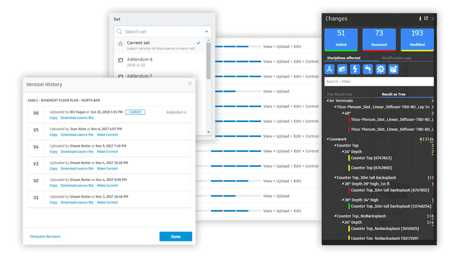
    Collaboration for Revit customers that maintain active subscriptions to BIM 360 Design will retain access to their projects and data in BIM 360 Team and will also have access to the BIM 360 platform with new and improved features and workflows including greater file- and folder- based access controls, unlimited storage, facilitated model exchange, and change visualization.

    3. How will renewals be handled for BIM 360 Team?

    Existing BIM 360 Team subscribers will be eligible to renew their BIM 360 Team subscriptions at the same price. Customers that maintain active subscriptions to BIM 360 Team will retain access to BIM 360 Team projects and data and will also be provided access to the new BIM 360 Platform.

    If BIM 360 Team or Collaboration for Revit customers decide to NOT renew, upon the end of a subscription, all project files can be downloaded. Project data will be maintained in customer accounts after the end of the subscription for a period of time as specified in the Autodesk Trust Center.

    4. Will current C4R subscribers be able to continue to use the product as they do today?

    If you are an existing Collaboration for Revit subscriber and you maintain an active subscription of Collaboration for Revit, you can store, access, and manage project data and perform cloud worksharing in either BIM 360 Team or the new BIM 360 Platform.

    5. Which Revit versions will work with Collaboration for Revit and BIM 360 Design?

    • With Revit 2015 to 2018.2 and earlier versions, you can cloud workshare in Collaboration for Revit.
    • With Revit 2018.3, you can cloud workshare in both Collaboration for Revit as well as BIM 360 Design.
    • With Revit 2019, cloud worksharing will be exclusive to BIM 360 Design.

    6. Where can I find more technical information?

    The Autodesk Knowledge Network has published this guide to BIM 360 DesignContact our Support Desk if you need more information.