fbpx
  • Flow and Pressure Drop Calculations Available in MEP Fabrication Elements

    Have you noticed in Revit you have to choose between ducting and piping that supports flow propagation OR ductwork that is modelled for the intent of fabrication?

    In the 2024 release of Revit, Autodesk has made great improvements related to the fluid flow within fabrication elements, getting us one step closer to the single tool for both design and construction.

    Using Ductwork as an example I will show you the new functionality and point to some of the benefits of each approach to modeling in Revit MEP.
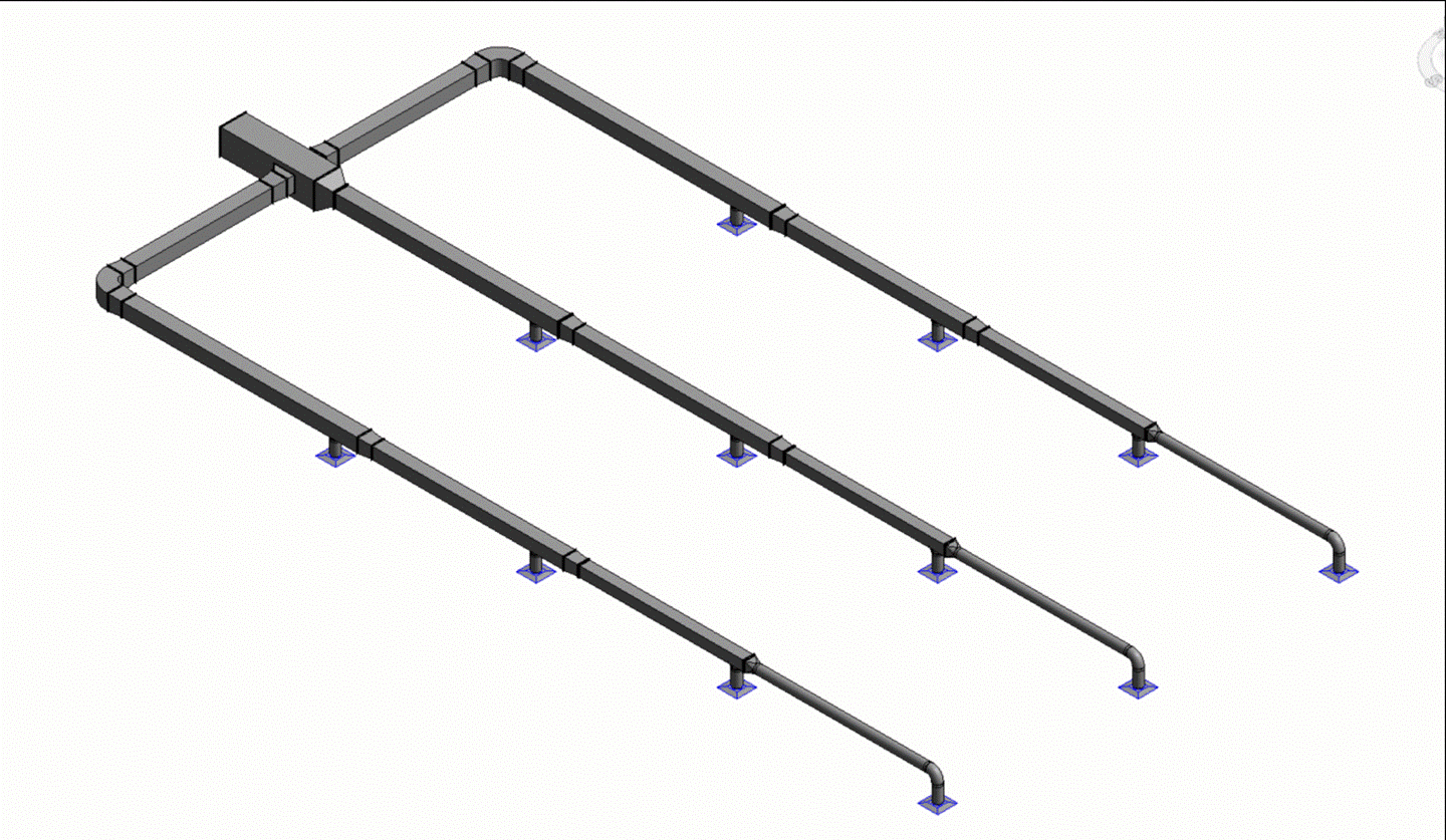
    Figure 1. Design and Fabrication Ductwork Interchanging

    Figure 1. Design and Fabrication Ductwork Interchanging

    One of the limitations of Fabrication Ductwork since its introduction to Revit in version 2016 has been that, once placed or converted from Design to Fabrication, you lose the design data within the model. No Flow values passed from the Air Terminals, Plumbing Fixtures, Equipment etc into the Fabrication elements. This meant that when the model was passed from the design consultant to the contractor – and they made the change to fabrication parts to enable them to export data out to a cutting table or spooler – they would have to manually calculate future changes in flow values to make sure the ducts were ideally sized.

    This differs to the design elements, where the flow, duct size, fluid velocity would all be visible within the design elements, making a change to the ducts dimensions immediately shows up with changes to the velocity, as would a change to the flow value of a downstream connected element.
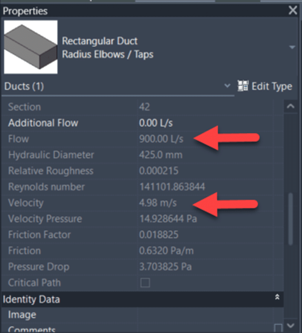
    In Revit 2024, Fabrication MEP elements now show all of the same information as the design elements:
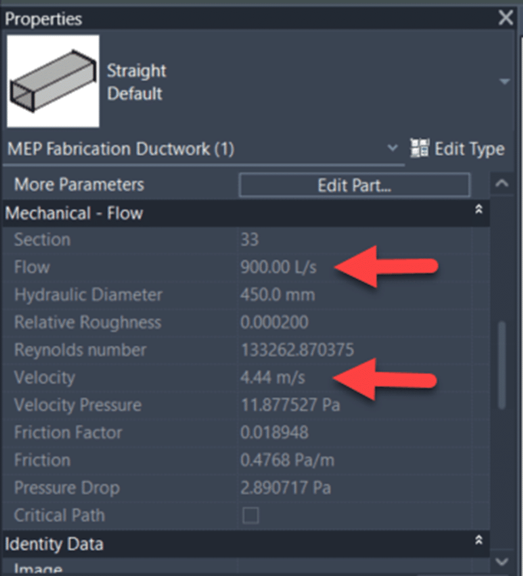
    For some reason they have neglected to include the simple Duct/Pipe Sizing tool for MEP Fabrication Ductwork, but you can get around this with a ductulator, or some simple Dynamo:

    Just kidding (on the simple bit), let me know if you want the Dynamo File, Its by no means complete, but it does some basic sizing of Rectangular MEP Fabrication Ductwork based on velocity, flow and cross sectional area.

    Another limitation is that the System Color Schemes do not show up for Fabrication elements, when you place a System Color Scheme into a view to show the Duct Velocity for example, you will see something similar to the below with Design Duct:

    But it has no effect on MEP Fabrication Ducts in the view… So while Design Duct has some knowledge of which systems are passing through it, MEP Fabrication Ductwork would seem to not have been made privy to this information.

    So how do we get MEP Fabrication Ductwork showing the flow value from connected Air Terminals in Revit MEP? Follow these steps in Revit 2024:

    1. Open Revit 2024.

    2. Start a new project based on the new Metric Multi-discipline template.

    3. On the Systems Ribbon Tab, Fabrication Panel, click the Fabrication Part tool.

    4. Click Settings in the lower right corner of the MEP Fabrication Parts palette.

    5. Select the ‘Fabrication Metric 8.0’ Fabrication configuration.

    6. Scroll down the unloaded services until you see the ‘HVAC: General Supply’ service, select it and click the Add button to move it to the Loaded Services column.

    7. Click OK to exit the Fabrication Settings dialog.

    8. On the Systems Ribbon Tab, HVAC Panel, click the Air Terminal tool.

    9. Open the L1 – Mechanical view.

    10. Select the ‘M_Supply Diffuser : 600 x 600 Face 300 x 300 Connection’ Family Type in the Type Selector and place it at an elevation of 2400 from L1.

    11. On the MEP Fabrication Parts palette, select the ‘Multi-Point Routing’ tool.

    12. Click on the top center of the placed Air Terminal.

    13. Set the Middle elevation in the properties to 3200.

    14. Continue to place more MEP Fabrication Ductwork, or finish the command.

    15. Select the Air Terminal and note the Flow value on the Options Bar.

    16. Select a piece of the connected MEP Fabrication Ductwork and note in the Mechanical – Flow properties there is a Flow value that matches the flow from the connected elements.

    To learn more about Revit, feel free to contact us and one of our representatives will reach out to you shortly.

    Parameter Jammer using Revit MEP and CTC Tools

    Are you a Revit MEP user and frequently download Revit content from manufacturers or sources like BIM Object? Once that content is loaded into the project, is there a struggle to get the family properly to work with your schedules? Well than the CTC Parameter Jammer tool is the one to help solve these problems.

    Downloading Revit family content regularly brings along shared parameters to your project that are different from your company’s standards. This will give inconsistent information within the schedules. Use Parameter Jammer to deal with those problems.

    Here is a schedule with a family loaded into a project but does not have information populated because of the inconsistent parameters from the family to the project.

    Run Parameter Jammer

    With a simple user interface, there a couple steps needed to map the loaded family’s parameters to match the project.

    • Select your companies shared parameter file
    • Select the schedule that the family will be residing in
    • Select the family/families that the parameters need to be modified

    In the next window, you will get a list of all the Shared Parameters from the selected schedule along with the family parameters. From the family parameter list, you will apply what needs to be done to the family. Parameter Jammer will also find same named parameters and automatically map them. When you select the drop-down list, you specify a family parameter to match the ones in your schedule. It will only show parameters that have the same units. You can also create a new instance or type parameter for the loaded family.

    A final report will be displayed to show what has been done.

    As you can see, downloadable content being used in a project does not need to have much modification for it to work properly in your current projects. Parameter Jammer gives you the ability to quickly grab information from the new loaded families and map those parameters to meet your company standards. Your schedules will be up to date and have no missing information in a matter of a few clicks using Parameter Jammer.

    CTC 2021 Revit Product Updates!

    CTC Software was actively preparing to release updates to our AEC tools for Revit 2021. This release took place on May 4th and affected all of our AEC offerings. HIVE has undergone a massive update, streamlining all aspects of user interaction and management. Our software suites have all been built to work on the new Autodesk 2021 platforms, and the SuperDoor Configurator and Casework Configurator content packs have been upgraded for 2021 as well.  All of these tools will continue to support the 2017 versions of Autodesk products and newer, so they will also fit into your workflows for any version from the last 4 years.  Additionally, the Mechanical Electrical Plumbing Productivity Pack content files have been upgraded to 2019, containing hundreds of updated families and a lot of new features and improved workflows.  These tools are purpose-built to support your entire workflow from beginning to end, putting the right tools in the right hands so all team members gain efficiencies every day.

    Contact CTC or one of our partners for more information about the 2021 updates to our tools!

    HIVE

    HIVE specifically has had major changes to the user interface of the content management system (CMS).  Many of you have provided feedback after extensively using the currently released HIVE system.  We listened!  The new HIVE has a major facelift, and the HIVE management portal on the web has been overhauled to make management easier, and to provide you with analytics for organization-wide use of CTC tools, project performance metrics and insights into how your teams are searching for content in the CMS.  As always, we strive to develop our tools alongside you, so you and your teams can work efficiently.  Feel free to share your experiences and ideas for how we can continue to improve.

    The other productivity tools in the software suites are all updated to work on the Autodesk 2021 platforms as well. This year we have decided to make sure that we support 5 version of Autodesk products, since we know many of our clients have projects with long lifecycles.  While Autodesk may not officially support 2017, we felt that we should continue to make our tools available for that release since some of you have let us know that your projects are still being managed in that version.  This new 2021 release of our tools will have the ability to communicate with the HIVE management portal so you can have a better understanding of the return on your investment this next year.

    CTC has 3 major Revit-based content packs.  The two that install into the ribbon are the SuperDoor Configurator and the Casework Configurator.  These, like our other suites, will be supported on Revit 2017-2021.  The other content pack, the Mechanical Electrical Plumbing Productivity Pack (MEPPP), has been heavily updated in its latest version. It will be supported on Revit 2019-2021 with the actual content delivered in Revit 2019 format.  We made this choice since most of the projects starting fresh in your firms will be on 2019 and later.  We did not see value in building on older versions, as existing projects in production do not see huge benefits in transitioning standards mid-production.  This MEPPP update has seen further standardization of the parameters used to help align our pack with metric users.  The first release will be in Imperial units of measure, but a metric pack will be coming soon.  This release saw heavy formula updates and further removal of unit dependencies.  The lighting fixtures, electrical equipment and mechanical equipment have seen major updates, improving face-based and level-based hosting in a single family, and general ease of use.  Many other categories have been touched as well, to ensure a uniform workflow and general consistent use.

    As always, we encourage you to contact us or our partners for more information on these workflow-improving tools.

    In the United States you can contact Applied Technology Group (ATG) at sales@ATGUSA.com. If you are are based in Canada, please contact:

    Mughees Altaf
    Account Manager — AEC Productivity Tools
    mughees.altaf@solidcad.ca 

    This article was created by CTC Software

    Revit 2019: Essentials for MEP Engineers

    Getting started with Revit can feel daunting. It’s an unfamiliar program that may not work like your current software. But, like anything new as you become more familiar with it you will start to see the benefits of the basic modifying tools – Copy, Move, Align, Offset, Mirror, Array – as well as the special tools it offers like Systems, Analyze, and Collaborate all within a 3D environment. Layers, often an irritation, don’t even need to be thought about in Revit. Revit will place every object in the correct layer. You do not need to switch Ortho on/off or change Snaps. Revit will show alignment lines, angles, snap points on the go.If you are just starting out in Revit, here is some basics that you should know:

    Model
    Revit creates a virtual 3D representation of the model with the established relationships between elements.You can create as many views as required by the project. Every view of the model is a live view of the parametric elements. If an element is moved in one view, the position of that element in all of the views is instantly updated. Therefore, changing the elements will change the model instantly and all changes will be reflected on each view and plot sheets.

    Model elements
    All of the elements in Revit are Families and represent real objects. Families are grouped and sorted by category in the content libraries and in the Project Browser. The families, such as air terminals, plumbing fixtures, and mechanical equipment, are loaded into the template of the project or into the model from the Revit library or an external source. For example, from the manufacturer’s website or Autodesk Seek. All Families in Revit are parametric.

    Instance and Type properties
    Model elements in Revit represent physical instances in a model. When placed in a model they are visible in all views.

    Type properties for the family are common for all types of the same family and contain information that applies to all instances of the same family type in the model. For example, type properties for an air terminal will be size – length x width. Changes made to type properties affect all instances of the family created from that type. Revit allows to change the family with a different type using the Type Selector. It is easy to create a new type within the family using the Duplicate function in the Type Properties dialog.

    Instance properties contain information related to a specific placed instance of the family element in the model. For example, instance properties for an Air Terminal will be Air Flow. Changes made to instance properties affect only that instance of the family.

    Annotation elements are also families that are used to add dimensions, notes, and tags to a view.

    The first Revit project can be a frustrating one. You will be learning the program while you are working on your project. Even if you had some training, you’ll quickly find that not everything will work like it did in your training sessions in a real project. All the elements are drawn to real size and you need to be attentive to clashes while working on your model.

    There are some little things you’ll want to remember:

    • Remember to place Air terminals or Electrical fixtures at the right elevation. Default for Air terminals is 0.000 and needs to be changed to match ceiling height. You also need to assign Flow to Air terminals.
    • As soon as you start a layout of the ductwork, Flow will be calculated through the system. You do not need to insert fittings working on ductwork or piping layout, Revit will do that for you.
    • Keep the section or 3D view of the area you are working on open. Don’t create sections just because you can; create one vertical and one horizontal, move them around as needed; create a new one when necessary and delete it once you are done.
    • When you have placed MEP elements into a model, you can generate a duct or pipe layout manually, or Revit can generate it automatically from different layout solutions.
    • A parameter that defines the system is the Connector that is located within model elements and has pre-defined classifications within Revit. If you cross two ducts or two pipes with the same system classification on the same elevation, Revit will join those systems by creating a fitting. If this is not what you intended, place the systems on different elevations.
    • One Model element can have a number of different connectors with pre-set system classification, so elements can be assigned to a number of systems. A set of logically connected elements creates a system.
    • All components and systems can be seen in the System Browser – a tool that displays a hierarchical list of all system components in each discipline in the model.
    • Annotations are view-specific; they appear only in the view in which they were placed. Annotations can be copied from view to view, but any changes made to them in one view will not be transferred to any other views.

    Now open Revit, select the System tool, drop some Air Terminals, place some ducts and now you can see the system you created in 3D. Wow! It looks impressive. But more impressive is the fact that you have not only created a system, and sized the ductwork with one click, you have also produced a section and a schedule which will be updated as you are working on the model. Revit has the ability to perform calculations such as pressure loss and static pressure, size ducts and pipes, and perform energy analysis on the design.

    Contact us to find out more about Revit for MEP and how we can help you get the most from it.


    Using Curtain Walls for Wall Panel Systems

    This video examines one of the best features Revit has to offer: curtain walls. We will look at how to use curtain walls for exterior finishes – like metal panels – that are not curtain walls.

    During this video we will go through two examples that demonstrate how to use curtain walls for panel systems:

    • How to set up a curtain wall to have it schedule and tag like a real wall.
    • How to gain the benefit and flexibility of the curtain wall grids and panels.
    • How to create a curtain wall for an exterior louvre façade.