fbpx
  • Civil 3D: Profile Grade Intersections

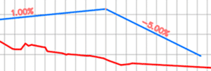
    The goal in this example is to design the profile where each grade is an even number.  It’s not as obvious as you might think.  Thanks to my colleagues Dave Hill and Jae Kwon for pointing out the proper tool.

    Read on to learn more…

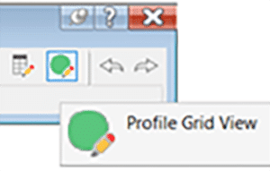
    Begin by modeling the first 2 segments.  I’ll assume you know the best tools for this, but I’ll give you a hint.  Use the Grid View; it’s your friend here.


    To model the last 5% grade is not entirely obvious.  Yes, a 5% tangent can be drawn from the end of the 1% grade, but it doesn’t end in the right place.

    We sort of want to draw backwards from the end of the red profile then extend the 1% grade.

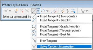
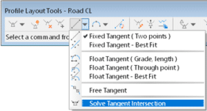
    Use this tool and follow the prompts.  First select the 1% grade, then pick Station and Elevation and the tie-in point.  Then enter the grade, in this case -5% (the grade from the intersected PVI).


    C’est voilà!

    Civil 3D: Profile Grade Intersections

    The goal in this example is to design the profile where each grade is an even number.  It’s not as obvious as you might think.  Thanks to my colleagues Dave Hill and Jae Kwon for pointing out the proper tool.

    Read on to learn more…

    Begin by modelling the first 2 segments.  I’ll assume you know the best tools for this, but I’ll give you a hint.  Use the Grid View; it’s your friend here.


    To model the last 5% grade is not entirely obvious.  Yes, a 5% tangent can be drawn from the end of the 1% grade, but it doesn’t end in the right place.
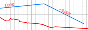
    We sort of want to draw backwards from the end of the red profile and then extend the 1% grade.

    Use this tool and follow the prompts.  First select the 1% grade, then pick Station and Elevation and the tie-in point.  Then enter the grade, in this case -5% (the grade from the intersected PVI).
             

    C’est voilà.


    Civil 3D: Model Existing Underground Utilities Efficiently

    Civil 3D: Model Existing Underground Utilities Efficiently

    Must you draw existing gas, tel, and other similar underground utilities for your projects?  If you’re not using the technique described below, you’re using too much time!  Read on to find out more.

    Join us at Infrastructure University, session 3, on October 20th for more information about this technique. For now:

    Facts:

    1. For nearly every civil engineering project, we must identify existing features on our construction drawings so they may not be disturbed during construction and so we may design proposed works without conflicting with these existing features. They must appear in both plan and profile.
    2. It can take considerable time to draw and label them in the plan, and even more project them into profile.
    3. When there is an edit to the alignment, the profile locations must be recalculated, taking more time.
    4. Experiments have shown that it can take 84 seconds to draw each utility. Then 26 more seconds each when the alignment is edited.
    5. Using the technique described below, the time is reduced from 84 seconds to 20 seconds. But 0 seconds when the alignment is edited.
    6. For 160 utilities:
      1. 3.7 hours using the manual technique.                   69 minutes each time the alignment is edited.
      2. 53 minutes using the automated technique.         No extra time when the alignment is edited.

    Method

    1. Create pressure network parts lists, one for each utility. Assign styles accordingly.
    2. Create pressure networks, one for each utility. Assign the parts list and label styles accordingly.
    3. Model the existing utilities as pressure networks and project them into profile. The depth below ground can be automated.