We are excited to announce that our partner CTC Software released Civil 3D CIM Project and Manager Suites, version 22.0.1. It is now released and can be accessed on the CTC website.
This update saw a lot of fixes and enhancements to new products released in 22.0.0 and before.
Below are release notes:
22.0.1
8/17/2021
CIM Project Suite
Pipe Planner
Bug Fix
Fixed a variety of issues causing Pipe Planner to error out or crash. Improved application speed performance. Fixed issues with exporting to external spreadsheets. Fixed issues with importing external spreadsheets.
22.0.1
8/17/2021
CIM Project Suite
Pipe Planner
Enhancement
Added support for formulas in user-defined empty columns and rows. Added properties filter search bar. Added interactive selection of export starting cell. Improved part renaming, allowing old names to be reused on new part names within the same operation. Added new right-click options to edit the middle table. Misc. enhancements and performance improvements.
22.0.1
8/17/2021
CIM Project Suite
Pipe Designer
Enhancement
Improved part renaming, allowing old names to be reused on new part names within the same operation.
22.0.1
8/17/2021
CIM Project Suite
Label Genie
Enhancement
Added option to manually select anchor objects in drawings. Added option when labeling layouts to create a unique layer for each layout.
22.0.1
8/17/2021
CIM Project Suite
Label Genie
Bug Fix
Fixed an issue where layout-specific labeling was not respecting exact viewport extents. Fixed an issue where segment labels were not following the assigned layer. Fixed misc. issues with specific drawing files.
22.0.1
8/17/2021
CIM Project Suite
Earthwork Processer
Bug Fix
Fixed an issue where errors occurred if existing or proposed surfaces were empty or not overlapping one another. Fixed an issue where earthwork region polylines that were significantly small would not offset and cause the app to error.
22.0.1
8/17/2021
CIM Project Suite
Data Wizard
Bug Fix
Fixed an issue where survey figures caused Data Wizard to error.
22.0.1
8/17/2021
CIM Project Suite
Parts Swapper
Bug Fix
Fixed an issue where parts not found in the parts catalog were causing Parts Swapper to file.
22.0.1
8/17/2021
CIM Project Suite
Corridor Mapper
Bug Fix
Fixed an issue where changes to assemblies would cause the app to error.
22.0.1
8/17/2021
CIM Project Suite
CIM Project Suite
Bug Fix
Fixed an issue where custom subassemblies were breaking when CIM Project Suite was installed.
22.0.1
8/17/2021
CIM Manager Suite
Template Tracker
Bug Fix
Fixed an issue where pressure network band styles were causing Template Tracker to error out.
22.0.1
8/17/2021
CIM Manager Suite
CIM Manager Suite
Bug Fix
Fixed an issue where custom subassemblies were breaking when CIM Manager Suite was installed.
ne powerful feature in Bluebeam Revu I think everyone should be using in some capacity is Layers.
If you come to Revu with a CAD background, you probably understand and use Layers already. For those who don’t, you just don’t know what you don’t know. I hope this article helps shed light on a new opportunity to add flexibility, organization and clarity to your PDF workflows.
For those old enough, Layers could be described like this: Remember in grade school when the teacher used the overhead projector to show things on the wall or pull-down screen? The surface of the overhead is the PDF when you open it. The clear film they write and draw on is a layer. That layer can be taken off or hidden, turned back on, or you could overlay several different layers to see them all on the screen.
In Revu, we can isolate categories of markups or flatten them. If you’re not familiar with the Flatten function, refer back to this previous blog post.
You might be asking: “Where do we find Layers?” There are a few places.
First, let’s look at the Panels on the sides of the Revu interface. You should see a black vertical bar on the side with several panel tabs toward the top. Right-click below the tools and hover over “Show.”
There, you’ll then see a list of Panels; click on the Layers option. When it turns blue, that means it’s visible.
Another place you will see Layers is, when you open a document printed from drafting/design tools, they will often transfer from the original file. To quickly see what Layers look like and how they can be powerful, try the Overlay Pages tool. If you’re not already using Overlay Pages when revisions cross your desk, brace yourself.
Here are some quick definitions of how Layers could be used for different phases of the project lifecycle.
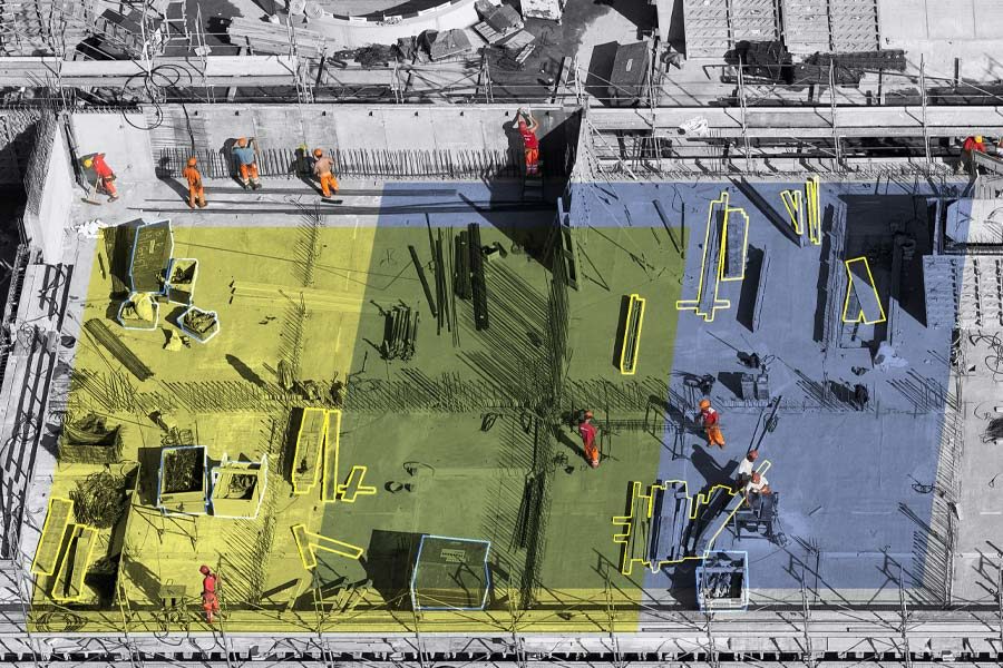
Planning: When planning a new construction development, you might use Layers to break down different elements of design requirements. For example, you might have individual Layers for building area, parking, green space, etc.
Design Review: During the design and review phase, you might have Layers and colors indicating markups needing to be added to the drawings, markups which are just comments to the drafter for reference or internal notes for design intent. You might even have Layers to track first-round markups and another for additional comments after the backcheck.
Estimating: When I build custom tools for estimating, I like to always include Layers to break down systems or material types. I always reverse engineer the tools and think about how I might manipulate the Layers when the sheet is full of markups. You might want to turn off all the flooring area measurements so you can see all the transition strips.
Hiding all the concrete slabs will make it easier to see and select the isolated footing, or maybe you only want to see the continuous strip footings. Layers allow you to isolate materials so you can build out the estimate without having all material Layers on at the same time.
Site Preparation: On the civil design side, you might want to get quantities and differentiate cut-and-fill areas indicating what materials can be reused someplace else on site. If you’re recording progress with site images or survey points, you might organize those by date as well.
Construction: During construction, we can use Layers to break down your schedule. Looking at the estimating markups, you could determine how many concrete trucks come each day and isolate the curbs, slabs and footing accordingly. You could also use it for site logistics locating material deliveries, job trailers and portable toilets on site with a date layer. Knowing what needs to move on site as the project progresses can keep everyone informed on expectations.
As-Builts: When on site recording existing conditions, P&ID or verifying installation, Layers can be used to indicate new vs. existing, supply vs. return, gas vs. water piping or to indicate valves that need to be replaced.
Facility Management: When tracking so many systems in a facility, it can help to keep them all in one drawing and use Layers to organize them. When all the Layers are on, it might seem like an organized mess, but when you isolate the low voltage layer to investigate a network problem, suddenly it’s clean and precise. After you solve that emergency, you might switch Layers for a plumbing issue or verify the dates on fire extinguishers.
Extra Credit: Incorporate Layers so those markups you do early in a project are still used downstream, eliminating redundant work. I’ve worked with several specialty contractors building tools for the sales team to layout while walking a site with the owner. All the devices are built with pricing, so they immediately have an estimate.
Those same markups are moved and revised by the engineering team back in the office, with the estimate being updated automatically. When revisions pass through, they have direct visuals of scope creep and price increases. These markups can also be used by the installation team on site, changing the status of each device as they complete the install. In Studio Sessions in Revu, the project manager knows in real time how much work remains on site, helping him schedule the next project.
As you can see, there are many powerful ways to use Layers throughout all phases of a construction project. I hope you found this introduction to Layers in Revu helpful and you have some new ideas of how you might implement them into your workflows.
With Lumion, you can render more than a building. Render your client’s dream home, render a story about design that moves emotions, render the space where life happens.
A building begins as a structure. Walls. Floors. Roofs. Windows and doors. All expertly crafted into a beautiful arrangement of form and function.
When looking at the 3D model, however, you might feel as if something is missing. Maybe it doesn’t capture the energy and atmosphere of the space and its surroundings. Perhaps it doesn’t ignite emotions or make you want to be there. Whatever it is, there’s something about life that’s just not easy to show in CAD.
With Lumion, you can bring your vision to life and tell a richer, more immersive story about the design’s role in the real world. A story that sparks imagination and helps clients fully visualize how life could unfold within those four walls.
From the small experiences you share with others to the objects that decorate your home, life is full of feeling. The sofa, coffee table and chairs in the living room, for instance, become a gravitational center where families share peaceful moments together. Papers and pens and books are scattered across a busy home office desk, alongside used coffee cups and photos of loved ones. In the kitchen, the teapot boils and toast pops out of the toaster, signaling the start of a new day.
These are not just objects, they are reflections of life. They fill spaces with character.
Lumion helps architects unveil their designs as lived-in spaces, capturing the deeply personal connection between a building, the people who inhabit it, and all the unique objects they bring with them.
You can render more than a building. Render your client’s dream home, render a story about design that moves emotions, render the space where life happens.
What’s new in Lumion 11.5
The latest version of Lumion reinforces its ability to make spaces feel alive with the everyday activities that occur there. You can let your imagination loose and tell a story about a room, a building, or even the entire project, exactly as you see it in your mind’s eye.
Lumion 11.5 Pro comes with 123 new objects* in the content library, making it easier to add a human, personal touch to your renders. You can find 73 new retro-inspired objects that reveal the unique identity of spaces, including:
36 eye-catching kitchen objects, including blenders, refrigerators, toasters, mixers and more.
12 furnishings from another era, including café tables and chairs, a jukebox, a popcorn maker and more.
11 timeless pieces of office furniture, including sofas, desks, chairs, table lamps and more.
14 other stylish items, including clocks, radios, a sewing machine, TVs and more.
Additionally, you can express delight throughout your scene with 50 new 3D characters, including a diverse variety of children, teens and adults of different backgrounds and cultures.
These cheerful non-animated characters are ideal for communicating context, scale and emotion in the background of your project, whether it’s a sunbather relaxing on the grass, a child looking up with wonder, or a couple enjoying a beautiful view together.
There are infinite stories to tell about your design with the mix of new 3D characters and retro-inspired objects in Lumion 11.5. When combined with Lumion’s existing content library of over 6,300 assets* and over 1,250 materials*, you’ll find yourself on a smoothly paved road to rendering creativity, to bring your designs to life.
Availability
Lumion 11.5 is available from June 1st, 2021, as a free update for Lumion 11 and Lumion 11.3 users. Lumion 11 users can download the updated version on your Lumion Account.
We are excited to announce that our partner CTC Software released Civil 3D CIM Suites for version 2022. It is now live and can be found on the CTC website.
The update can be downloaded from the about menus in the apps.
For network licensing you will of course need new license files, which can be requested here: LicenseRequest@ctcsoftware.com.
Standalone licensing has been updated already for current subscriptions.
This release saw support updated to 2019-2022, a major new app for pipe networks, a completely rebuilt app for corridors, and many new features and fixes across the majority of the tools and both suites.
Release notes for CIM suites 22.0.0:
Version
Date
Suite
Component
Type
Detail
22.0.0
6/24/2021
CIM Project Suite
Pipe Planner
First Release
Load pipe networks in an in-app spreadsheet or export to external spreadsheets. Edit parameters and perform analyses in the spreadsheet then push changes back to the pipe network. Create customized manhole schedules, pipe depth reports, and detailed QTO.
22.0.0
6/24/2021
CIM Project Suite
Corridor Mapper
New Features
Completely rebuilt the legacy Corridor Mapper tool to a new app. Corridor Mapper version 2 allows for linking of subassemblies to styles and object names. Can also now select multiple subassemblies at once an assign targets to all of them. Subassemblies can now be mirrored to other subassemblies, so that when the source one changes all the dependent subassemblies update with it. A default surface can be assigned for surface targeting so that as new surface type subassemblies are added to the corridor their surface target will automatically assign. Users can filter out objects by type. Manual selection of targets has been added. A list of current targets is now available to view targets assign automatically and manually to a given subassembly.
22.0.0
6/24/2021
CIM Project Suite
Auto Grader
Bug Fix
Fixed an issue where loading certain grading family templates caused an error. Fixed an issue where parent features lines being added to a surface in template insertion family types were causing odd surface behavior. Fixed an issue where naming a child grading component “parent” would cause the app to crash. Fixed an issue with template grading families where deletion of template feature line and subsequent running of a family referencing that template would result in deletion of all child feature lines.
22.0.0
6/24/2021
CIM Project Suite
Auto Grader
Enhancement
Added support for partial station ranges to wrap around the end of closed parent feature lines. Added option to duplicate “split” points in parent features lines as PVIs in child feature lines. Added option in child feature line formatting when grading existing feature lines to “keep source” of existing feature lines. Added option in stations settings where users can specify the starting station to increment from, opposed to it always being 0+00.
22.0.0
6/24/2021
CIM Project Suite
Auto Grader
New Feature
Added new feature for template insertion grading families, where Distance at Slope and Distance to relative Elevation methods can have the template insertion elevation determined by adjacent feature lines, and not just the parent feature line. This allows for smarter placement of grading pads relative to surrounding lot elevations.
22.0.0
6/24/2021
CIM Project Suite
Pipe Designer
Bug Fix
Fixed an issue where using cancel to escape out of the app would not allow a network license to be returned.
22.0.0
6/24/2021
CIM Project Suite
Parts Tagger
Bug Fix
Fixed an issue where using cancel to escape out of the app would not allow a network license to be returned.
22.0.0
6/24/2021
CIM Project Suite
Data Wizard
Bug Fix
Fixed an issue where when object counts were zero the app would error when trying to create a table. Fixed an issue with embedded grids where scrolling didn’t work correctly.
22.0.0
6/24/2021
CIM Project Suite
Earthwork Processer
Bug Fix
Fixed an issue where surface styling defaults in Options would uncheck “match default” when rebuilding earthwork sets. Fixed misc. issues where app settings were not saving correctly for future sessions within the app. Fixed an issue where the app errored on incorrectly drawn polylines.
22.0.0
6/24/2021
CIM Project Suite
Earthwork Processer
Enhancement
Added option to multi-select region rows for mass editing. Added zoom in drawing buttons for each region. Improved the region row visibility when earthwork sets are expanded. Improved messaging when illegal subgrade boundaries are utilized. Improved label placement to use largest area placement instead of centroid. User edits to labels will now not be overridden when earthwork sets are run, including label placement.
22.0.0
6/24/2021
CIM Project Suite
Earthwork Processer
New Feature
New supporting function to all creation of automatic offsets of user-created polylines or feature lines. Users can reference existing region objects by manual selection or filtering and specify an offset distance to quickly create subgrade regions that do not overlap.
22.0.0
6/24/2021
CIM Project Suite
Label Genie
Bug Fix
Fixed an issue where auto-feature lines could not be selected in the drawing. Fixed an issue where erroring occurred when trying to save a template. Fixed an issue where app errored when running line and curve labels. Fixed an issue where the Required Object field for surface type labels was not reseting correctly. Fixed an issue where unfound label styles were causing the interface to glitch. Fixed an issue where child styles for some categories were not appearing in the style lists. Fixed an issue where manual text overrides performed prior to using label genie were being erased.
22.0.0
6/24/2021
CIM Project Suite
Label Genie
Enhancement
Improved user guide explanations for drawing source and label selection behavior.
22.0.0
6/24/2021
CIM Project Suite
Parts Swapper
Bug Fix
Fixed an issue where using retain size option would not properly allow parts to swap if those parts were not found in the parts lists and/or had identical descriptions for multiple part sizes.
22.0.0
6/24/2021
CIM Manager Suite
Layer Boss
Enhancement
Added legend in import results to better understand the different color coding of results. Added column header filters to excel export.
22.0.0
6/24/2021
CIM Manager Suite
Layer Boss
Bug Fix
Fixed an issue where the layers export dialog box wasn’t stretching components correctly. Fixed an issuye where, when the user settings in the user appdata folder did not exist, the app would error out. Fixed an issue where french color spellings were not recognized when export to or syncing from Excel. Fixed an issue where the description column would sometimes be empty when exporting to Excel. Adjust button order on import function to be more industry standard.
22.0.0
6/24/2021
CIM Manager Suite
Layer Boss
New Feature
Add a new column to the excel export titled “New Name”. This will allow users to change layer names in excel, then upon syncing back to the dwg, the layer name will change, but all references to that layer will stay intact.
22.0.0
6/24/2021
CIM Manager Suite
Linetype Manager
Bug Fix
Fixed an issue where certain .shx files could not be read. Fixed an issue where some linetypes would not import. Added support for include periods (.) in the linetype name.
22.0.0
6/24/2021
CIM Manager Suite
Survey Template Manager
Bug Fix
Fixed an issue where block references in point styles were not updated when exporting to Excel. Fixed an issue where multiple description key sets were appearing in the app, but did not exist in the drawing.
22.0.0
6/24/2021
CIM Manager Suite
Template Tracker
Bug Fix
Fixed many issues where certain mleaders, layers, text styles and dimension style references were not found in the drawing. Fixed an issue where sorting by layer in layer editing dialog box caused an error. Fixed an issue where certain drawings would cause a looping error when opening Template Tracker. Added support for Pressure Network related references can now be tracked (2022 version only).
Do you use BIM 360 and AutoCAD products? Do you have the Autodesk Desktop Connector installed? If so, there is a new update. This may not be news to you as there are frequent updates, but this one is somewhat unique. Please read on.
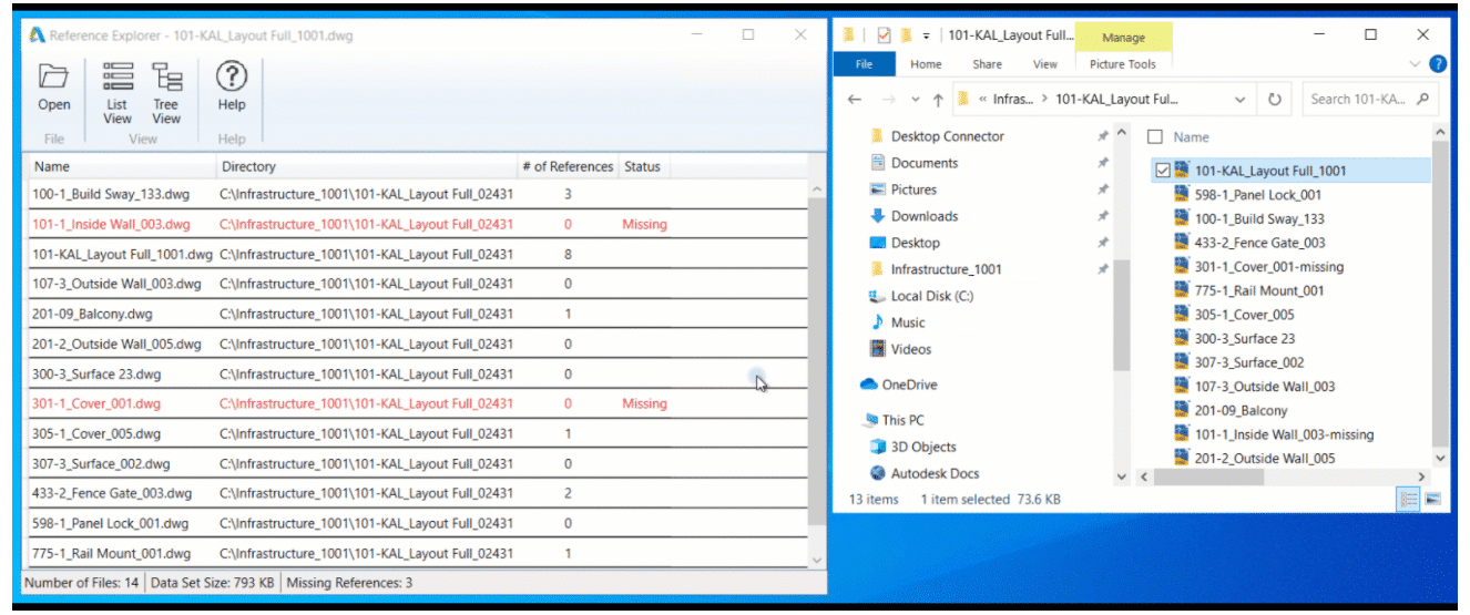
The new Reference Explorer provides the ability to visualize all files in a dataset as well as the relationships between the files before or after uploading to the cloud.
Resolved Issues:
DST files will not open, and content is incomplete after the DST file is saved to the workspace, or when synced from the cloud.
Increased the number of concurrent files in download workflows to increase performance.
Fixes, and of course new features are included with this update. Here are the release notes. Read on to discover what’s new.
Fixes
There have been many defect fixes and you can read about them here. The one notable item I’ll describe here is about feature lines. Some users have experiences them magically disappearing from some drawings. Here is an excerpt form the documentation:
“Errors that will lead to missing feature line issue are automatically detected and fixed when opening a drawing. This operation will only run when Civil 3D detects a potential error in the drawing.”
Use the Insert Points at Crossing Locations command to insert PIs or elevation points on crossing feature lines in the same site.
Use the Set Grade/Slope Across Feature Lines command to edit the grade or slope between vertices on two or more intersecting feature lines.
Use the Set Corridor Baseline Elevation by Reference command to set the elevation of a point on a feature-line-based corridor at a given grade or slope from a specified location. This command adjusts the elevation of the corresponding PI on the corridor baseline accordingly.
Autodesk Collaboration (BIM 360):
Support has been added for reference templates and sheet set data files.
ArcGIS:
Refresh an ArcGIS dataset in your drawing so that it matches the ArcGIS dataset online and add new Civil 3D objects to ArcGIS.
Pipe Networks:
Gravity network analysis has 2 new settings:
Pipe Length Type which you can use to specify the pipe length type to use for the analysis calculations.
Conservative Travel Time that you can use to specify whether the minimum velocity or the calculated design velocity will be used to calculate the pipe section time if the design velocity is smaller than the minimum velocity.
Digitizing plan documents is only as effective as your ability to access them as you work. Digital dashboards in Bluebeam Revu make it easy to do both
While completely digitizing document management remains among the construction industry’s determined priorities, the challenges of truly becoming fully digital don’t stop there.
Once a contractor completes its transition from paper-based workflows and processes to a 100% digital document environment, the next challenge often is determining the quickest and most efficient way to facilitate the proper distribution of plan documents to all project stakeholders during its lifecycle.
Even though having an entirely digital document management system is inherently more organized and efficient than a paper-based one, issues around folder structure, file access and viewing permissions are tedious and painstaking problems to solve.
Enter digital dashboards.
A digital dashboard is a visual interface that allows for easy access and navigation to a project’s digital document ecosystem. Whether someone is working in an office, jobsite trailer or in the field, digital dashboards allow all project participants a simple way to find, access and view relevant plan documents at the point of need—without having to navigate complicated folder and file structures.
Digital dashboards are especially powerful for users of Bluebeam Revu, as the platform’s features for viewing, marking up, storing and collaborating on construction documents are made even more optimal by adding the proper visual interface.
Michael Echave, a senior AEC technical specialist with industry consultancy ATG USA, is a big advocate of digital dashboards. He’s worked with clients in a variety of subsectors in the industry as they seek to finalize their digital document transformations by integrating visual interfaces to make project documents more accessible to workers spread across big and complex jobsites.
Keep the end in mind
According to Echave, there are many ways to create a digital dashboard to serve as a project’s document and reference materials navigation hub. Essentially, a dashboard is a hyperlinked page in itself where designers can create buttons and other interface elements to lead users to find plan documents stored in folders in a platform like Studio Projects in Revu, Bluebeam’s document storage capability.
“You want your end goal in mind when you start to build a dashboard, and then you start peeling back those layers,” Echave said.
There’s also a lot of flexibility in where dashboards are built. Of course, Bluebeam Revu is one option, using the markup tools to create navigable buttons that link to subfolders within Studio Projects or other document storage systems.
An ATG project dashboard homepage.
Once construction professionals have determined the program they’ll use to build the dashboard, it’s important to determine how many layers of navigation the dashboard will include. Dashboards can be as simple as having one homepage with several links to single-layered subfolders, or they can include several layers of complex subfolders that lead to different types of documents and reference materials, such as websites or other online resources.
What’s more, a project may have multiple dashboards. For instance, field workers might work off a simplified dashboard for easy access, while engineers, designers or architects in the office may decide to have a more complex dashboard at their fingertips.
Regardless, Echave said every dashboard will include a home page that features different links, or “actions,” that serve as clickable buttons. These buttons bring users to different subpages that help them refine their document search. Buttons can lead to PDF documents or entirely different applications or websites. The image below is an example of an ATG digital dashboard home page:
Each subpage will include more interactive links, allowing users to navigate to even more subpages in the dashboard. The free storage in Bluebeam Studio Projects makes the possibilities of layers and subpages virtually endless.
Critical steps to building a dashboard
Pick a background
Digital dashboards can be elegantly designed with compelling visuals or made simple with solid color backgrounds. Consider who the user will be for the dashboard when determining its design. Workers in the field may prefer a more straightforward design, Echave said, while architects or design professionals may find more complex design elements more engaging.
Echave said when building dashboards, he typically uses an 8.5 X 11 for his border size. Then he inserts a logo.
Use markup tools
Next, Echave advises using markup tools such as rectangle, ellipse or polygon to place shapes that are colored and filled.
Ultimately, this is the opportunity to consider how the dashboard’s subpages will be organized, which will inform the layout of the home page. Also keep in mind that the homepage will also serve as a template for the different subpages.
Create links
Using the text box markup in Revu, create links to different subfolders. Echave said images can also be used as links. Make sure that interactive icons and clear fonts are used as well, Echave said; this keeps the dashboard visually appealing for users.
With the layout complete, add links to the static actions. For instance, the area highlighted in the image below will never change in any of the dashboard’s subpages. Users can also add static popup windows.
Copy page to add multiple subpages
Once this initial template is built, it can be copied via the thumbnails panel in Revu. Echave said to create as many subpages as needed to organize the digital dashboard. Users can also save text boxes or any markup into the Tool Chest as a custom Tool Set to allow users to replace them later on or on future dashboards.
Once the outline has been copied for the dashboard’s intended page count, Echave said users can then start to reorganize each subpage, such as Site Plan and Submittals.
After all subpages have been reorganized, Echave said it’s now time to add the link to the text boxes or images.
Avoid broken links
Avoid broken links by double-checking that every link works. One thing to keep in mind: if links go to local files on a computer, other users won’t be able to access them. Cloud-based storage like Studio Projects in Revu is ideal.
When using Studio Projects, Echave said it’s important to set the proper project folder permissions. Project partners who do not have access to Revu can use a free 30-day trial to collaborate in the dashboard; after that, Revu will convert to view mode, allowing users to continue accessing Studio.
Finally, if dashboards are created in Studio, construction professionals can send out email invitations to different project partners, giving them access to the digital dashboard.
Maintain throughout project
Once the dashboard is fully deployed on a project, Echave said it’s critical that it is maintained throughout the project’s duration. Keep it updated by refreshing it with the latest documents while ensuring that no links have been broken along the way.
Do you use more than one CTB file when printing in AutoCAD? More than 10? 40? What if I said you really only need 1, the Monchrome.ctb file? Read on to find out how…
If you already understand CTB files, feel free to scroll down to the heading “Do This Instead”.
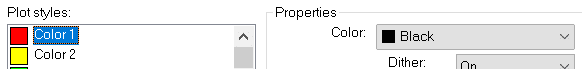
Let’s look at what we have to work with:
1.AutoCAD users use various colours.
2.Typically, the colours used are chosen from this 256-colour “Index” palette.
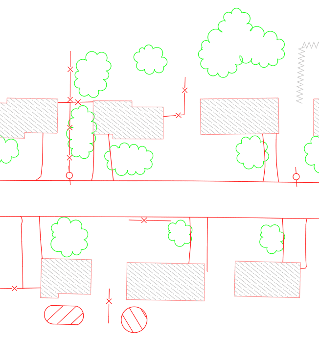
3.Those colours on the screen don’t always print that colour.
4.Linework need to print to varying widths.
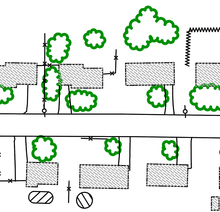
On-Screen:
Printed:
CTB files are the intermediary between the drawing on screen and the final printed product. If one is not used, what you see on screen is what is in the print. They are used to transform what is seen on screen to what is displayed in the print.
Many AutoCAD users rely on several CTB files to print documents to various regulatory standards. Here is why…
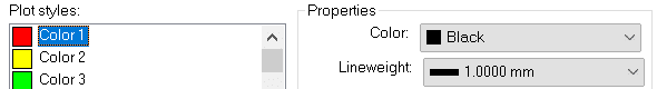
The City of SolidCAD requires a sanitary sewer layer to be red on screen but print black and thick (1mm).
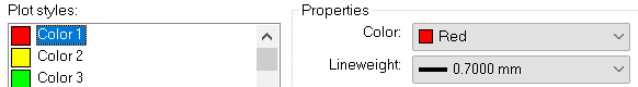
The District of Cansel requires that same sanitary layer to be red on screen but print red and not so thick (0.7mm).
42 other standards exist and a unique CTB file is required for each of them.
Here is the SolidCAD CTB file:
Here is the Cansel CTB file:
THESE ARE NOT REQUIRED!
Yes, that was a little tongue-in-cheek. Sometimes you’re sent a file and you just need to print and use the available CTB. But if you have the time, inclination, and desire to make things a little easier on yourself, understand it’s possible.
Do This Instead
The solution here is actually very simple. Follow these steps.
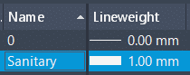
1.Set the line weight properly for the layer based on the regulatory body standard.
2.Use the out of the box monochrome.ctb file. This file prints all 256 Index colours in black.
How to print hat sanitary layer in red when the CTB file prints all colours black, you ask? Well, I didn’t say the CTB prints all colours black, just the 256 Index colours.
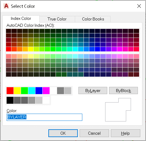
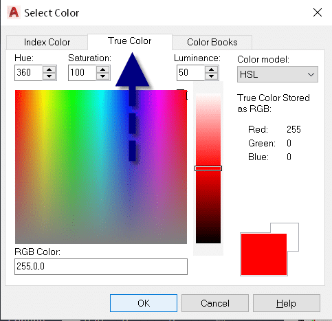
3.When colour is required set the layer colour, not to one of the 256 Index colours, but to one of the 16.7 million True Colours.
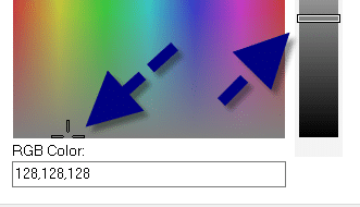
4.You need to print a grey shade? Again, choose a True Colour; just choose a colour at the very bottom. Use the slider on the right to control the shade.
You see, the CTB file does not control the output of True Colours, only the 256 Index colours.
Working on a job that requires numerous PDF files to be collated into one manageable document? It’s easy with Bluebeam Stapler.
What is Bluebeam Stapler? Among other things, it’s a tool that helps users combine individual PDF documents into a single PDF. It can also batch convert a variety of document types, such as PDFs, Word docs, and Excel spreadsheets, into a single PDF file.
If you’re working on a job that requires numerous PDF files to be collated into one manageable document or master file, and you’d like those files to be added to or amended, Bluebeam Stapler makes the tasks easier.
Settings and the organization of the individual PDF files can be saved as a stapled job for future use, saving time and resources.
Illustration by Nico Abbasi
Making life simple
Once a file has been established, updates to individual PDFs—which would usually involve creating a combined PDF again—can be done by opening up the previously created staple job, organizing the documents in the way you wish, hitting “staple”—and voila.
Using Bluebeam Stapler helps your working life be more straightforward. It means not having to worry about slip-sheeting individual PDFs into the original PDF to replace outdated pages.
It’s really useful when compiling a large document, such as a calculation package comprising many component PDFs.
Easy to use
The system’s interface is easy to use. One of the easiest ways to use it is “drag and drop.” You can take the files that you want to combine into a single PDF, select them, drag them over to the window, where you will see the normal Bluebeam combined PDF dialog.
Naming PDFs using a numerical prefix makes identifying the files easier, as does showing the date that each file was last updated.
Once you have everything where you want it, you just hit “staple.” The system automatically combines those PDFs, uses the file names of the individual PDFs and can bookmark those for you. Settings are also saved.
If you want to update a couple of these files in the future, all you need to do is open up the file using the staple job file. It will automatically combine all those files in that single PDF again.
Combination benefits
You can create a master file, which will have a combined PDF package and can be easily bookmarked for future use. You can have as many or as few bookmarks as you like.
Combining PDF documents used to take hours, not least when a document had possibly hundreds of individual PDFs that needed to be brought together.
Using Bluebeam Stapler speeds up the process and helps increase efficiency. It’s that simple.
Autodesk has released the latest version of their Civil Engineering package, Civil 3D 2022, and its partner in crime, Infraworks. Click to peruse the Autodesk Documentation. Recap 2022 has also been given some new features. Read on for some notable features.
Civil 3D
Grading Optimization: Takes the parameters that you have specified and generates, very quickly, an optimal grading solution. After installing Civil 3D 2022, you’ll find sample files in the folder C:\Program Files\Autodesk\Grading Optimization 2022\samples.
Connected Alignments: Supports complex curve groups, offsets from parent alignments, curves larger than 180-degrees, and calculates the cross fall of the associated profiles.
Project Explorer: Pressure networks are now supported. Multiple languages are now supported.
Infraworks
Road Decorations: Allows users to add decorations to component roads or linked corridors from Civil 3D. The InfraWorks model will display the features more quickly compared to previous releases.
Decoration Library: Now users can create more realistic landscape environments to add to the model context.
Bridge: Provides for the definition of full-span complex parametric 3D bridge girders.
Model Builder: Enhanced with a new and streamlined interface to provide a more consistent experience and improve usability.
Recap
Scan to Mesh: Select all or a portion of a point cloud in ReCap Pro 2022 and have it create a low, medium, or high-quality mesh. This was included in a previous version as beta software, but it was removed. It is back!