L’article de blog d’aujourd’hui présentera des outils qui accélèreront la production de vos designs de Projets 3D, qu’ils soient des corridors routiers, des intersections ou des tranchées d’excavation.
Nous utiliserons activement les outils Corridor Cleanup, Mapper, Splitter et Merger de la suite d’outils CIM Project développée par CTC Software.

Séparer et fusionner vos projets 3D
Lorsqu’on planifie notre design de corridor, qu’il soit simple ou complexe, avec ou sans intersections, utilisant différents profils types en simultanés appliquées sur multiples « régions », nous sommes dans l’obligation de penser au produit final pour optimiser notre performance de travail. Souhaitons-nous :
- Avoir toutes les rues d’un nouveau quartier afin de produire un calcul unifié des quantités de matériaux pour notre projet?
- Séparer en différents projets 3D nos intersections, fourches et cul-de-sacs de sacs pour simplifier logiquement la création de notre design?
- Séparer ou non notre quartier en phases de construction au sein de différents projets 3D?
Pour un concepteur de Civil 3D, ces questions auront une importance capitale dans son design. Retourner en arrière pour fusionner ou séparer des projets 3D représente des heures de travail, à redéfinir les éléments suivants:
- Lignes de base,
- Régions,
- Cibles,
- Paramètres de fréquences,
- Surfaces dynamiques.
Les outils Merger et Splitter de la suite CIM Project offrent une alternative ultra performante, qui permettra en quelques clics de sous-diviser et assembler des projets 3D, peu importe l’évolution dans le temps du projet.
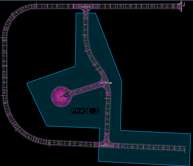
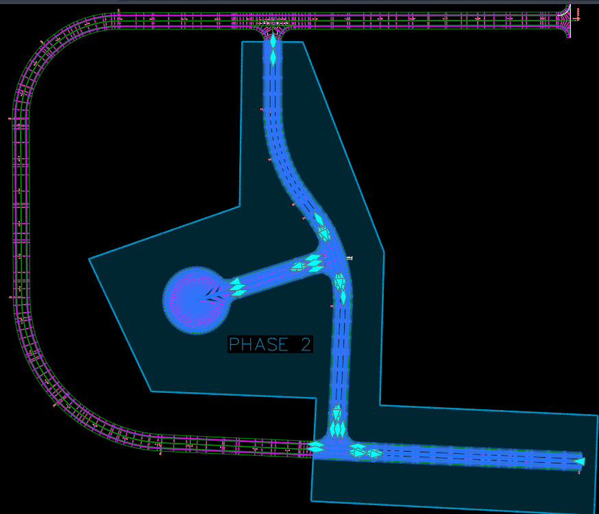
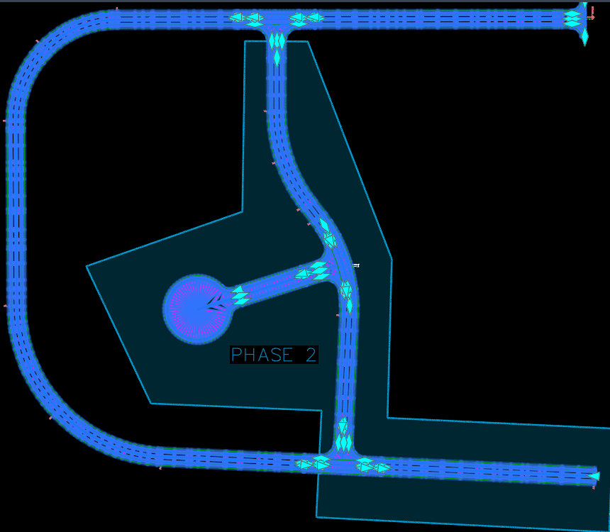
Voici un projet 3D en un seul morceau couvrant tout un petit quartier qui, en cours de projet, doit être divisé en deux phases de construction :
 Voici une idée des éléments à considérer et à redéfinir dans cette séparation (et la liste peut encore être déroulée…) :
L’outil Splitter permet de diviser en deux parties un projet 3D par ses régions ou lignes de base, tout en préservant les éléments discutés plus tôt qui servent activement à définir votre conception :
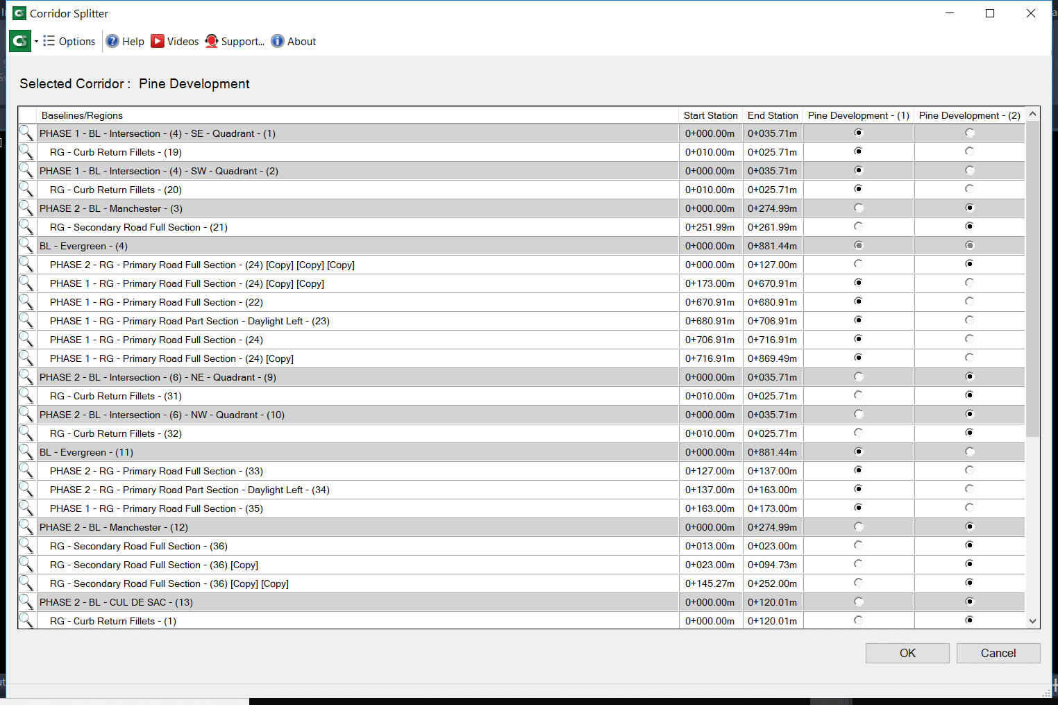
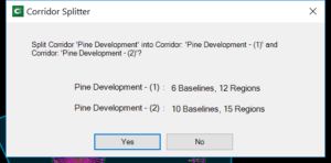
Voici le résultat final, en quelques clics :
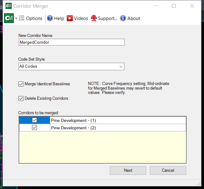
L’outils Merger fait exactement le même travail à l’inverse, fusionnant deux projets 3D et plus à la fois :
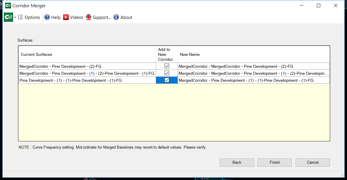
Vous pouvez optionnellement réintégrer les surfaces de corridors propres à chacun des projets dans le corridor fusionné :
Le résultat final réassemblé parle de lui-même, gardant intacte l’ensemble des paramètres de design de chacun des projets 3D à sa source :
L’usage des cibles dans les projets 3D : un outil simple à l’utilisation complexe
Tout design routier utilise activement des cibles de largeur ou d’élévation pour contrôler les valeurs variables des éléments de profil type (subassemblies), que ce soit pour ouvrir progressivement une voie de virage, former un cul-de-sac, former une intersection ou créer un élargissement pour un arrêt de bus.
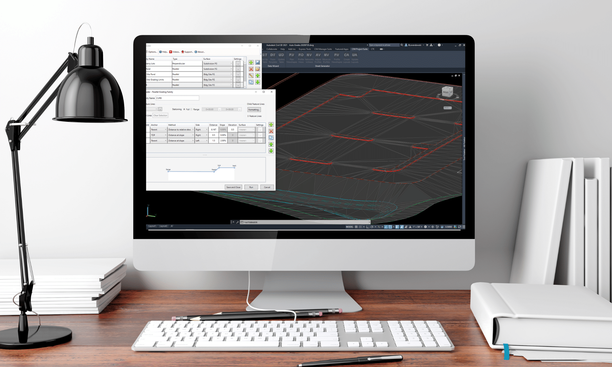
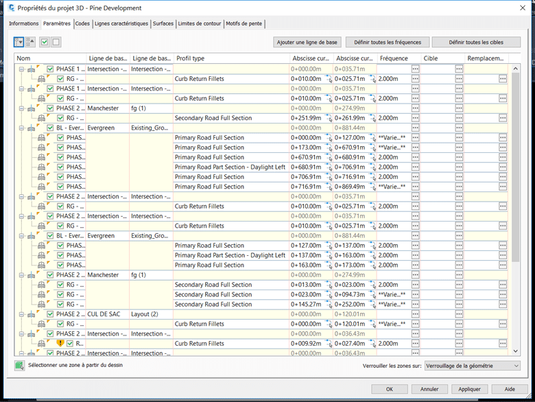
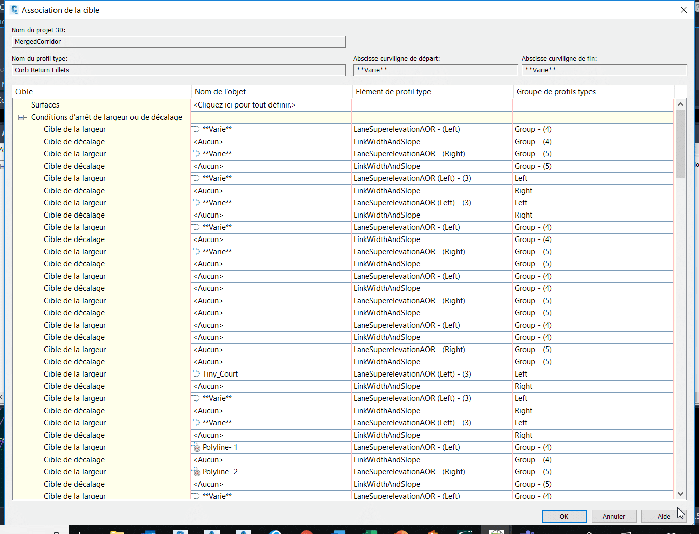
Dépendamment de la complexité de vos designs (en lien direct avec le nombre de lignes de bases et de régions au même endroit), la liste de cibles possibles peut être gigantesque. Peu importe sa taille, le concepteur passera une bonne partie de son temps dans cette interface à gérer les subtilités de son design :
CTC Software propose une alternative dans ses outils, appelée Corridor Mapper, pour sauver dramatiquement votre temps d’association de cibles, sans avoir passer par le menu précédent. Sa stratégie optimale, en fait, est d’associer des cibles situées sur des calques ayant les mêmes noms que les éléments de profils types, et ce dynamiquement (peu importe l’évolution du projet, si des cibles s’ajoutent, une simple mise à jour du lien remodélise le projet 3D).
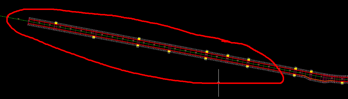
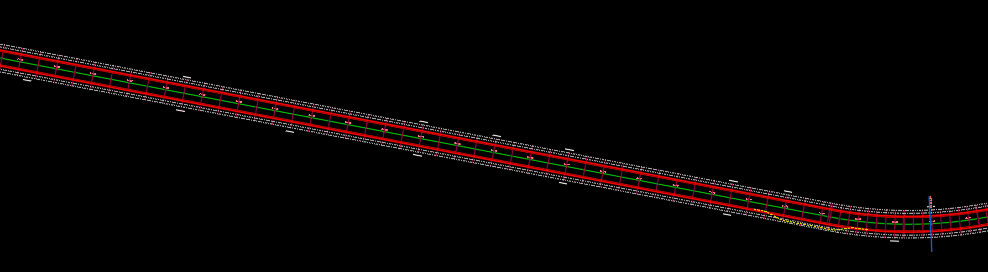
Dans l’exemple suivant, j’ai un corridor avec une condition de détection d’entrée de cours pour abaisser la hauteur des bordures de béton automatiquement (en rouge), ainsi que des polylignes qui créeront des élargissements de voies (en vert) :
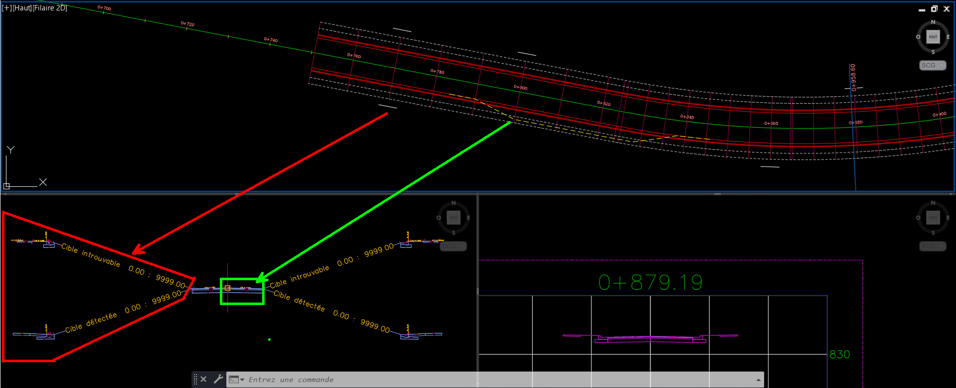
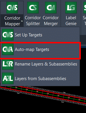
Corridor Mapper liera le nom de chacun de ces éléments de profils types (pouvant être personnalisés à la guise de l’utilisateur) à toutes les cibles placées sur des calques prédéfinis :
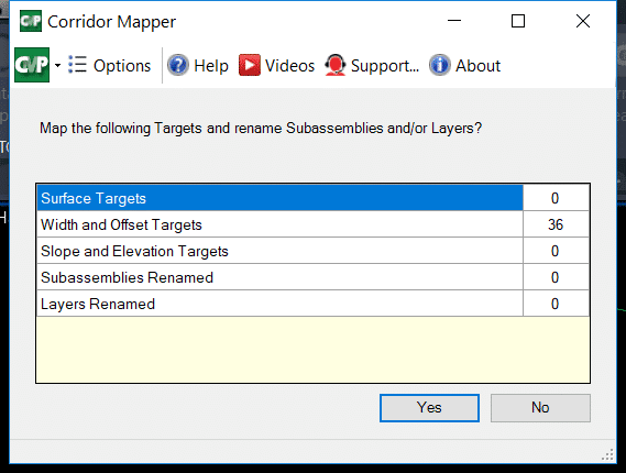
Si les calques à spécifier ont les mêmes noms que les éléments de profils types associés, les boutons Auto-Map Layers (en rouge dans l’image précédente) permettent de les lier automatiquement.
En quelques clics, voici le résultat :
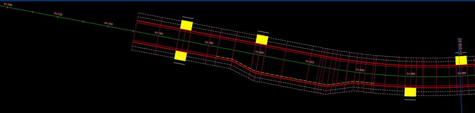
Et si notre projet évolue en augmentant de taille, doit-on refaire des manœuvres répétitives pour reliées nos nouvelles cibles?
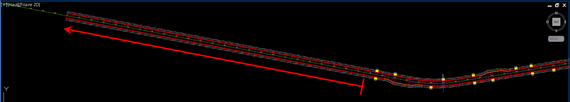
Non! Un simple clic sur le bouton Auto-map Targets passe en revu le contenu changé sur les calques des cibles pour mettre à jour le corridor :
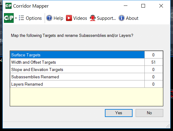
Pour un concepteur, on vient de se sauver facilement « une ou deux crampes au bras » par année en termes d’actions répétitives éliminées de cette façon. Voici le résultat :
Les outils « par défaut » de Civil 3D permettent également d’associer, à un temps donné, tous les objets sur un calque comme étant des cibles potentielles, mais les différences atouts qui démarquent Corridor Mapper sont :
- La liaison facile et efficace de cibles sur des calques spécifiques, dans une interface simplifiée sans aller-retours entre plusieurs fenêtres de paramètres;
- L’attribution automatisée de cette liaison lorsque les calques de cibles ont les mêmes noms que les éléments de profils types;
- La liaison dynamique d’un calque de cible et de l’élément de profil type associé.
Additionnellement, la fonction Corridor Cleanup permet de nettoyer les cibles d’un projet 3D en partie (soit par région, ligne de base ou même type de cible) ou en entièreté, permettant de partir sur de nouvelles bases lorsqu’on reprend un design que l’on souhaite altérer ou améliorer :
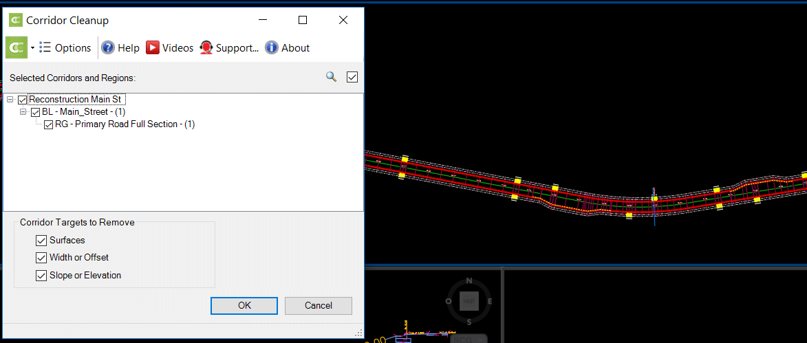
Voilà le résultat :
Conclusion
Le volet Corridors des outils CIM Projets nous sauvent un temps important en réduisant les manipulations répétitives sur l’édition de nos projets 3D. Peu importe la taille, la complexité ou l’évolution dans le temps de votre projet 3D, ces outils spécialisés vous permettront d’adapter très rapidement vos conceptions en génie civil. Vos concepteurs et chargés de projet vous en remercieront!
Pour en savoir plus sur la suite d’outils CIM Projects de CTC Software :
https://www.ctcsoftware.com/product/cim-project-suite-2021/
Vous trouverez également, au lien suivant, nos webinaires francophones en génie civil et infrastructures :
https://www.youtube.com/playlist?list=PLAhehuVvm9ky6D0jDNPuUd0JQelxgv3i3


 The Setting