Some people find that Revit files are using up too much storage on their server or other storage. Although a few companies have ‘limitless’ cloud storage this is not the norm. Plus, is anything really ‘limitless’ on this planet?
You might also want to refer to this post for additional info…
Backing Up and Recovering Revit Files
Revit files are large…fact. But surprisingly they are relatively smaller comparable to an AutoCAD project folder. The reason for this is that Revit contains more information efficiently in one file as opposed to a folder of many files i.e. AutoCAD, Sketchup, Excel etc. Still, your storage space may be used up WAY faster now than before Revit. Below are some possible culprits and recommendations. All of these recommendations are assuming that you have a server and local backup protocol.
1. Saving Local Revit files to server. Each person’s ‘Local’ file will eat space from the storage on the server. It’s better to have each user save the files locally on their machine. This frees up server space and acts as a backup. Saving Local Revit files to the server is made worse by many of the issues below.
2. Standalone Revit files are making too many backups. Turn the backup number down. Search for files with *.0*.rvt or a variation of that *.*.rvt. You may find many of these are redundant backups and can be removed.
3. Local Revit files are being ‘timestamped’ on open. This is when a Local Revit file is not overwritten on open, it makes another copy and appends the date and time to the name. If everyone is doing this, it will gobble storage space like candy. You might want to do the Overwrite option.
4. Revit Central files need to be Compacted occasionally. Do this in the Save Options. Also, keep the Maximum backups number down.
5. Large and messy CAD Files Imported or Linked. Sometimes a very large AutoCAD file will be brought into the Revit file. This will then get propagated to all the Local Revit files. The key here is to use AutoCAD to Purge and Audit ALL imported or Linked CAD before bringing it into Revit. Avoid bring CAD into Revit if possible. Put all Imports onto a Workset.
6. Large, messy, overly detailed or complicated Revit Families. Be suspicious of any Revit Families over 5MB. This is compounded if you need to use it many times. If the Family is well made it may be worth the pain for future information gains.
7. Revit file needs to be Purged. This command is dangerous if you just Purge everything. You will need to go through the list and pick out what needs to be purged. If there is a nasty Revit Family inserted into the project you will need to completely remove or replace it before Purging.
8. People are simply saving lots of copies of stuff. Sometimes people save every single Revit file they receive and every single copy they make. On the plus side, if it’s organised, you have a way to get old information that suddenly becomes very important. Or, it could just be unnecessary clutter. You should at least save a complete project folder at key project milestones.
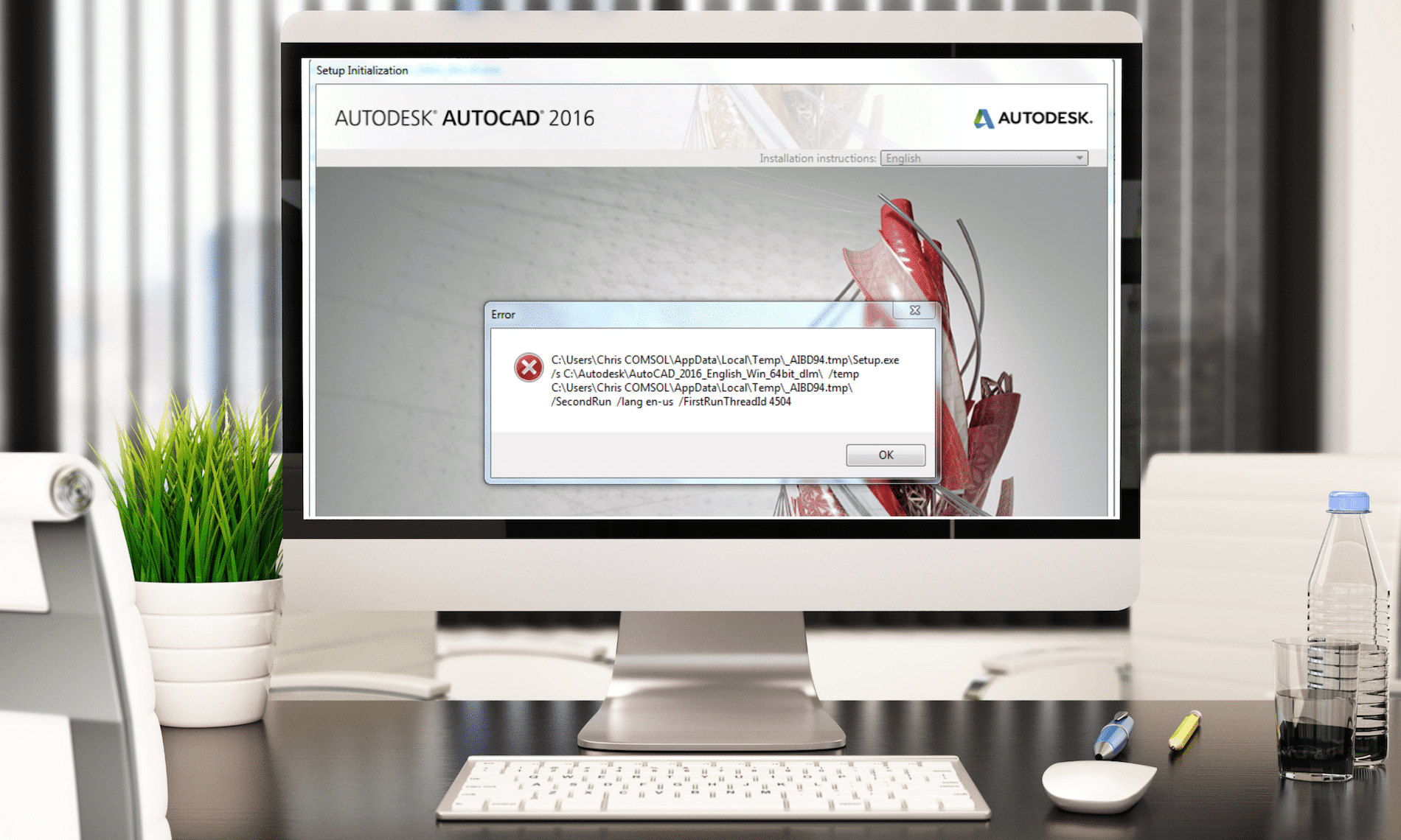
When starting Microsoft Office every time, AutoCAD runs for installation
Issue:
When starting Microsoft Office every time AutoCAD® runs for installation. Two error messages pop up: AutoCAD <version>: Please wait while Windows configures AutoCAD <version>
AutoCAD <version>: Run setup.exe to install AutoCAD <version>
Solution:
Repair your AutoCAD installation:
Start – Control Panel – Programs and Features
Select your AutoCAD version and choose from context menu “Uninstall/Change”
In the dialog select “Repair or Reinstall”
In the next dialog select the option “Repair” and click the button “Repair”
Want to know if your computer can run AutoCAD, Revit, 3DS Max, etc.. Instead of comparing your computer to a recommended system specifications, use the Autodesk Prerequisite Checker.
Although the new type of interface with Ribbons was introduced in AutoCAD 2009 to replace traditional Toolbars, there is still a large number of users who prefer Toolbars. Until and including AutoCAD 2014 it was very easy to restore them. All you had to do was to select AutoCAD Classic as the current workspace as seen in figure.
Things got more complicated starting with AutoCAD 2015. AutoCAD Classic workspace is no longer available, but luckily for those who prefer Toolbars, they are still included.
Solution:
One option is to transfer the AutoCAD Classic workspace from older customization file (ACAD.CUIX) to your current version of AutoCAD:
In your new version of AutoCAD type CUIIMPORT command and press Enter. The “Customize User Interface” dialogue box will be displayed with “Transfer” tab as current. The right half of the dialogue box will display the contents of the current version ACAD.CUIX file.
On the left half of the dialogue box, click the “Open customization file” button and select your older version ACAD.CUIX file with “AutoCAD Classic” workspace.
Using your mouse, drag and drop “AutoCAD Classic” workspace from the older-version ACAD.CUIX file on the left to the current version on the right.
4. Click OK to close the dialogue box
5. Set “AutoCAD Classic” workspace as current.
If you’ve been using Civil 3D for a while, than you’re probably loving the object tooltips!
There are two types of tooltips (Proximity and Rollover) for Civil 3D objects, which you can find from Civil 3D help documents.
So let’s review them!
Rollover
A rollover tooltip displays information about an object when you hover the cursor directly over it. If the object highlighting setting is on, the object will be highlighted when this tooltip is displayed.
Proximity
A proximity tooltip displays information about the current location of the cursor with respect to one or more objects in the drawing. More specifically, it displays information about the proximity of the cursor to the objects. These tooltips are displayed without having to hover the cursor over any specific entity in the drawing.
The most important object information is displayed at the beginning of the tooltip. For alignments and surfaces, the tooltip displays the station/offset information for the closest alignment to the cursor and the elevation of the topmost surface.
If you keep your cursor in the same location, additional information is displayed in an expanded tooltip that shows up to four more items. Which items are displayed depends upon the objects in the drawing and whether tooltips are enabled for that object. If there are five alignments and five surfaces in the drawing, for example, the proximity tooltip will display three alignments and three surfaces. Alignments are shown in order of proximity to the cursor. Surfaces are shown in order from highest elevation, to lowest elevation.
On the Toolspace Settings tab, right-click Surface –> Edit Feature Settings
Notice the “New Entity Tooltip State”
On: Sets the default state of tooltips for new objects to be turned on.
Off: Sets the default state of tooltips for new objects to be turned off.
Standalone and Workshared Revit Files are backed up and restored in completely different ways. Here is an explanation and some best practices…
You should probably refer to this blog post for additional info…
Revit Files are Clogging Up My Server Storage!
Standalone Revit Project Files
Revit makes *.001.rvt Revit files in the same Folder as the Revit File.
The amount of these backups are controlled by SaveAs-Options-Maximum. Every time you save, a backup will be created. The highest number will be the latest. In my opinion 3 is plenty. Default is 20, too many!
You can be reminded to save every so often by setting Application Menu-Options-Save Reminders. Set to 30 mins.
You can restore a backup file (*.001.rvt) by renaming (remove the .00) it and opening it. So as an example a file called PROJECTA.001.rvt would be renamed PROJECTA.rvt.
Workshared Revit Project Files
Does not have *.001.rvt like Standalone.
You can be reminded to save every so often by setting Application Menu-Options-Sync to Central Reminders. Set to 30 mins.
There is a Local backup folder in same location as Local Revit file. It contains files that you shouldn’t touch. You can set the amount of steps a Local Revit File can be rolled back in SaveAs-Options-Maximum. The default is set to 20. Best practice, set to 5.
There is also a Central backup folder in same location as the Central Revit file. It contains files that you shouldn’t touch. You can set the amount of steps a Central Revit File can be rolled back in SaveAs-Options-Maximum when creating the Central. The default is set to 20. Best practice, set to 5. High numbers will use a lot of server space.
Things to keep in mind about Restore Backup:
Backups are restored from Collaborate-Restore Backup for either Locals or Centrals.
Restore Backups cannot be undone.
Cannot reconnect to Central if you are separated even if you ‘Restore Backup’.
For these reasons I rarely recommend using Restore Backup.
If you get a corrupt Central Revit file, use one of the Locals to re-create a Central. This almost always is the best option. If all the Locals and Central are corrupt, send the Central Revit File and Journal Files to Autodesk and wait (about a week) to get an older restored version returned to you. If you can’t wait that long, go to your general server backups and get yesterday’s Central file. I haven’t seen too many corruptions in my 10 years of Revit consulting.
If a user ignores the Sync to Central reminders long enough they will disconnect from the Central. They will lose their work as there is no way to reconnect. So Sync to Central every 30 mins.
For every project, we either use out-of-the-box styles or create new styles to meet specific requirements of the company we work for or the project we are working on.
Once they are included in our template, we have everything covered, right?
But what if you need to display a property of an object that isn’t available under the Label Style Composer? Or maybe we want to display the label in a different way based on a certain value of the object?
First, let’s take a quick look at the fundamentals of the Expressions.
Expressions are located under the Settings tab of the Toolspace, under the Label Styles folder. (See Picture Below)
The New Component dialogue box consists of a number of components that are used to create the Expression.
In the Name field enter a relevant, identifiable name for your Expression
The Expression field will contain all the formulas and properties as the Expression is developed.
Buttons that may be used to aid in the development of the Expression (you can enter by the keyboard if you prefer)
The available object properties that may be inserted in the Expression field.
Functions that may be used in the development of the Expression
Choose how the results of the Expression are to be formatted. Usually always Double. (Unitless)
EXAMPLE
Let’s use an example and create an Expression that will truncate a pipe length label to the nearest 0.50 metre.
We get this request at times because not everyone wants the accuracy of a pipe length shown to the tenth of a metre.
To create the Expression right click on the “Expressions” and select New (See Image Down Below)
here are the STEPS
STEP 1:
In the dialogue box enter a name and description for the Expression that reflects the resultant label style. (Image 1)
STEP 2:
Pick the Formula button to expand the Expression Functions, in our case select the ROUND function (Image 2)
NOTE: The image to the right shows an arrow pointing to a button that inserts the ROUND function to the Expression window.
STEP 3:
Next we need to add the Object Property by picking the Object the Properties button and picking the appropriate Property.
In our case we will select 2D Length-Center to Center which is automatically inserted into the Expression window. (See Images Below)
Now we just need to add a little more math to complete the Expression and then click OK.
STEP 4:
The new Expression will be displayed in the Preview window of the Toolspace>Settings tab under the Pipe Label Styles and is now available to be applied to a pipe label
To add the Expression to the Label Style create a New pipe Label by copying and editing an existing style.
STEP 5:
Copy the default Length Description and Slope label style and rename it Rounded Length and Slope (See Picture Below)
[/vc_column_text]
Then select the Layout tab and in the Text section on the Contents row pick the corresponding cell in the Value column and pick the Ellipse button to access the Text Component Editor. (As seen in the picture below)
[
In the preview window of the Component editor highlight the “2D Length…” string and press delete to remove it from the label.
STEP 6:
In the Properties section pick the down arrow and locate the “Pipe Length to Nearest 0.5m” Expression that was created, set the Precision to 0.1 and click the UPDATE arrow to update the label in the preview window.
Click OK twice to closer the Component Editor and Label Composer.
Apply the new pipe label to the pipe object and the center to center length with be rounded to the nearest 0.50m.
When starting AutoCAD with standalone license the following error appears and software does not start:
“The security system (Softlock license manager) is not functioning or is improperly installed” (screen shot attached)
Causes:
There may be several reasons for this error, but most likely it’s the FLEXnet Licensing Service which is stopped or disabled.
Solution:
Go to Control Panel – Administrative Tools and double-click Services.
Find “FLEXnet Licensing Service” and “FLEXnet Licensing Service 64” (depending on the system, only one of the two may exist).
Right-click on “FLEXnet Licensing Service” and select “Properties”.
Set Startup type to “Automatic”.
Under Service status click “Start” button.
Click OK.
Repeat steps 3-6 for “FLEXnet Licensing Service 64”.
PDF created from AutoCAD shows frames around text in PDF viewer
Issue:
When viewing a PDF from AutoCAD in a PDF viewer, such as Foxit Reader or Adobe Reader, frames are displayed around text.
Causes:
Text frames are displayed by the PDF viewer and are not an inherent feature of the PDF or something that AutoCAD did in its creation. By default, frames are displayed in Foxit Reader and are turned off in Adobe Reader. The frames indicate there are comments linked to the affected text.
Solution:
In AutoCAD 2017 and later, a new system variable, PDFSHX, has been added
– Set PDFSHX to 0
In AutoCAD 2016, a new system variable, EPDFSHX, was added to address this issue with, AutoCAD 2016 Service Pack 1 :