• Canadian Flag Proudly Canadian Operated
  • SolidCAD earns Autodesk’s Top Service Delivery Partner Award

    Toronto, ON, March 9, 2021 – Yesterday, SolidCAD was named Top Service Delivery Partner Worldwide at this year’s Autodesk’s Platinum Club Awards, an event where Autodesk specially recognizes and appoints their partners globally for their hard work and efforts to service and support Autodesk products.

    Among other leading partners across the globe, SolidCAD remains one of the major Platinum Partners and professional services company in Canada. Offering over 80 training courses, 12 specialty consulting services and a large specialized technical team with years of industry experience, SolidCAD continues to provide their clients with the highest-level of support.

    “We are excited to achieve such a valuable recognition,” states Marcus Tateishi, President of SolidCAD. “We have an unbelievably strong team of talented sales professionals and support and services team.  We are grateful, that the Autodesk channel community recognizes it as well. This achievement proves that SolidCAD is a worldwide leader, helping clients overcome challenges with design, production, collaboration and project deliverables through our extensive offerings.”

    “It is great seeing one of our top global partners being recognized for their hard work and dedication,” Vikrant Saini, Partner Manager at Autodesk. “Our goal here at Autodesk is to deliver a world-class customer experience and our partners like SolidCAD allow us to do that at scale with their talented team of professionals. It is an honor to be part of the extended team at SolidCAD and can’t wait to achieve more together.”

    If you are interested to learn more about SolidCAD, visit them on Autodesk Service Marketplace to view all of their consulting, automation, training, product specializations and support services here: servicesmarketplace.autodesk.com/provider/public/solidcad

    Autodesk Inventor: Get A Different Perspective

    In this modern age of software, it seems that there is a specific software or tool for just about anything, but our main asset for accomplishing our CAD work is still our eyes. The way we view things has a major impact on our workflows.

    CAD work

    The common navigation tools inside Autodesk Inventor can become second nature. There are many ways to go about navigating around a model and every user has his preferences. Some use the Navigation Bar, some use the View Cube, some use the F keys or the mouse wheel just to name a few. Out of all the navigation options we have one command is more than often left out and that is Perspective View.

    Why using the Perspective View?

    Perspective View projects the model’s view to a vanishing point adding perspective and parallax in the scene. This gives a better comprehension of space, depth and volume. This helps create a more realistic and compelling view for any conception. While this effect is used widely for visualization and rendering, most users pass on its most useful asset:  navigation.

    While working in parallel projection (Orthographic) we can work precisely on our model without the distortion of a real-world view. This is where most work is done. But sometimes the geometry we are working on becomes our obstacle. One might have to work inside of something requiring creating hide situations on some parts to access the working area or create section views to access very small space in between geometry.

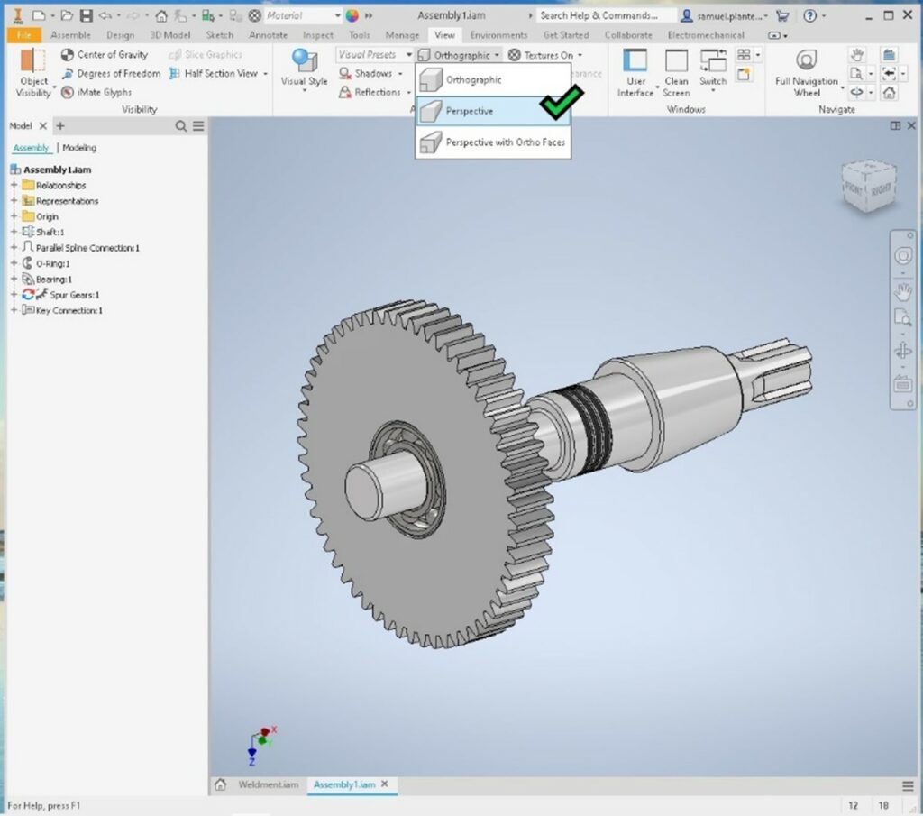
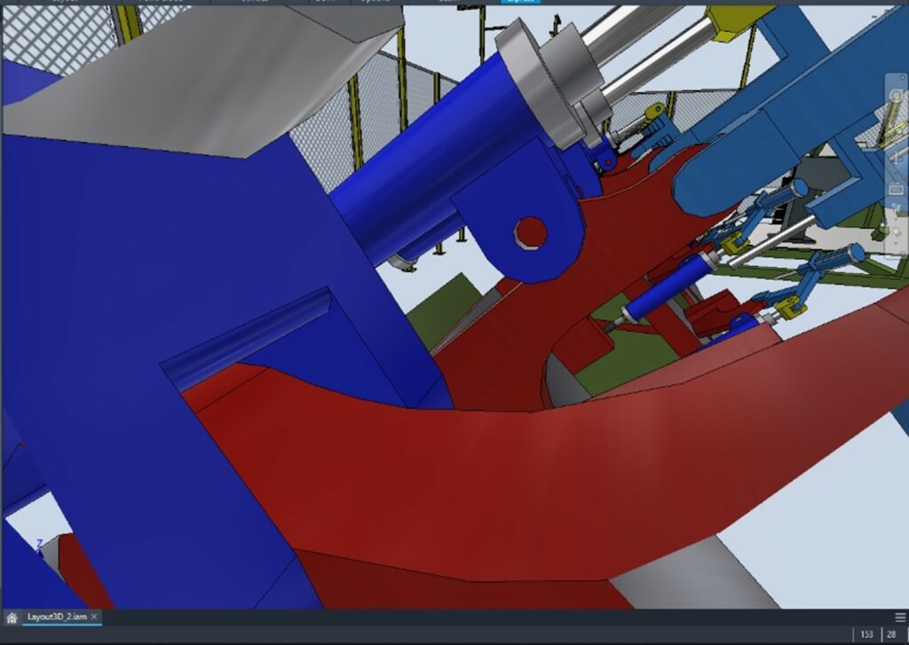
    These situations require the creation of work planes, adding extra sketches in our model, creating and managing view representations or just plainly utilizing commands such as Slice Graphics repetitively. All these manipulations are redundant and can soon become an irritant in a day-to-day routine. Here comes perspective to the rescue. Perspective view has a ghost behavior that enables the camera to go through geometry.


    You need to select a face inside an assembled drive shaft’s keyway? 

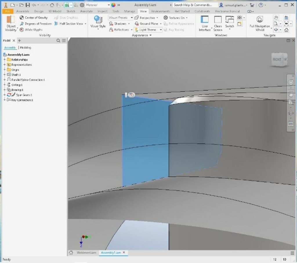
    Not a problem, just toggle Perspective on and navigate through the gearbox, gears and bearing to select the face you want. Simple!

    The images below show how we can go through the objects to select the inside face of a keyway without any other manipulation than a simple Zoom.

    Selecting a face with Perspective View
    Selecting a face with Perspective View
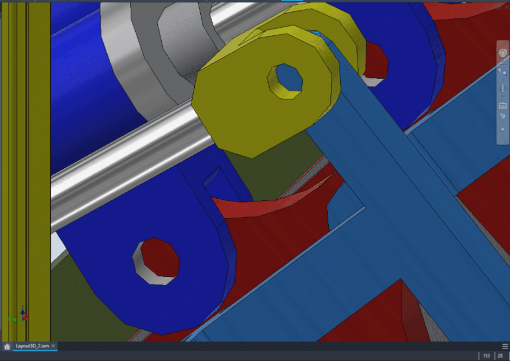
    What about working in a tight space? 

    Once again toggle Perspective on and navigate to the desired position.

    The image below shows the same viewpoint, one orthographic and the second in perspective. Obviously, the perspective view offers much more headroom with a better visual comprehension.

    orthographic view

    Perspective


    Here are my extra 3 tips for easier navigation of the Perspective View:

    1. While navigating in perspective view it is a good practice to select a model or a feature so that selection becomes the center of interest. This will make the navigation focused to that selection.

    2. The default zoom factor of the mouse wheel scroll is intended for broad movement. While in perspective, the dolly zoom might be a better companion. You can press F3 to activate this zoom on the fly or assign this zoom behavior to the mouse wheel in your preferences in Inventor 2021.

    3. To adjust the field of view of your perspective press Ctrl+Shift+F3 and click and drag in your viewport, you will notice that this increase or decreases your field of view. You can go from almost orthographic to a super wide-angle view with this option.

    Don’t get stuck in a sterile square world, push your horizon, widen your perspective and be more efficient!

    CTC & Feature Lines – Establishing the Hierarchy of Power!

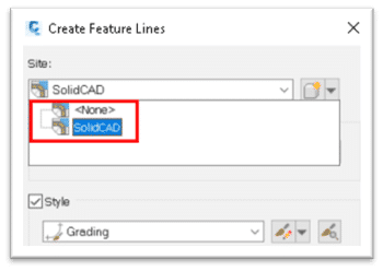
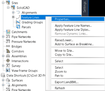
    Which option do you choose when creating a feature line? In my early days of learning Civil 3D I was given an analogy of buckets. That any of the objects in a site, “Bucket”, could not interact with other objects, this was the purpose of sites.

    This analogy was half-true and only the tip of the iceberg.

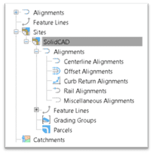
    For starters, sites can only house certain objects, and only parcels and grading groups are confined within sites.

    Alignments and feature lines have the option.

    The limited interaction between these “Buckets” only limits the interaction of the objects in a site from communicating with the objects in another site. That’s why we can choose to restrict feature lines and alignments.

    However, when feature lines are contained in a site, we have additional control over their interactions with one another.

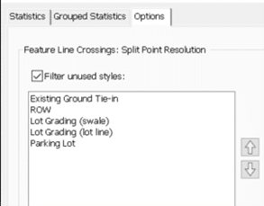
    This is called Split Point Resolution and it allows us to set which feature lines govern at a crossing. Assigning styles to feature lines, we can set which styles are the most important for the design.

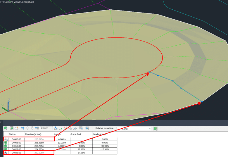
    I use this for lot grading to manage a variety of constraints and to make sure that right of way and existing elevations are respected.

    Using the split point resolution while grading this cul-de-sac, it ensures the lot lines obey the right of way and the existing tie in points.

    This technique can be used in many other grading scenarios like drops in a curb or pond access paths.

    It is a powerful concept that not many designers have embraced yet.


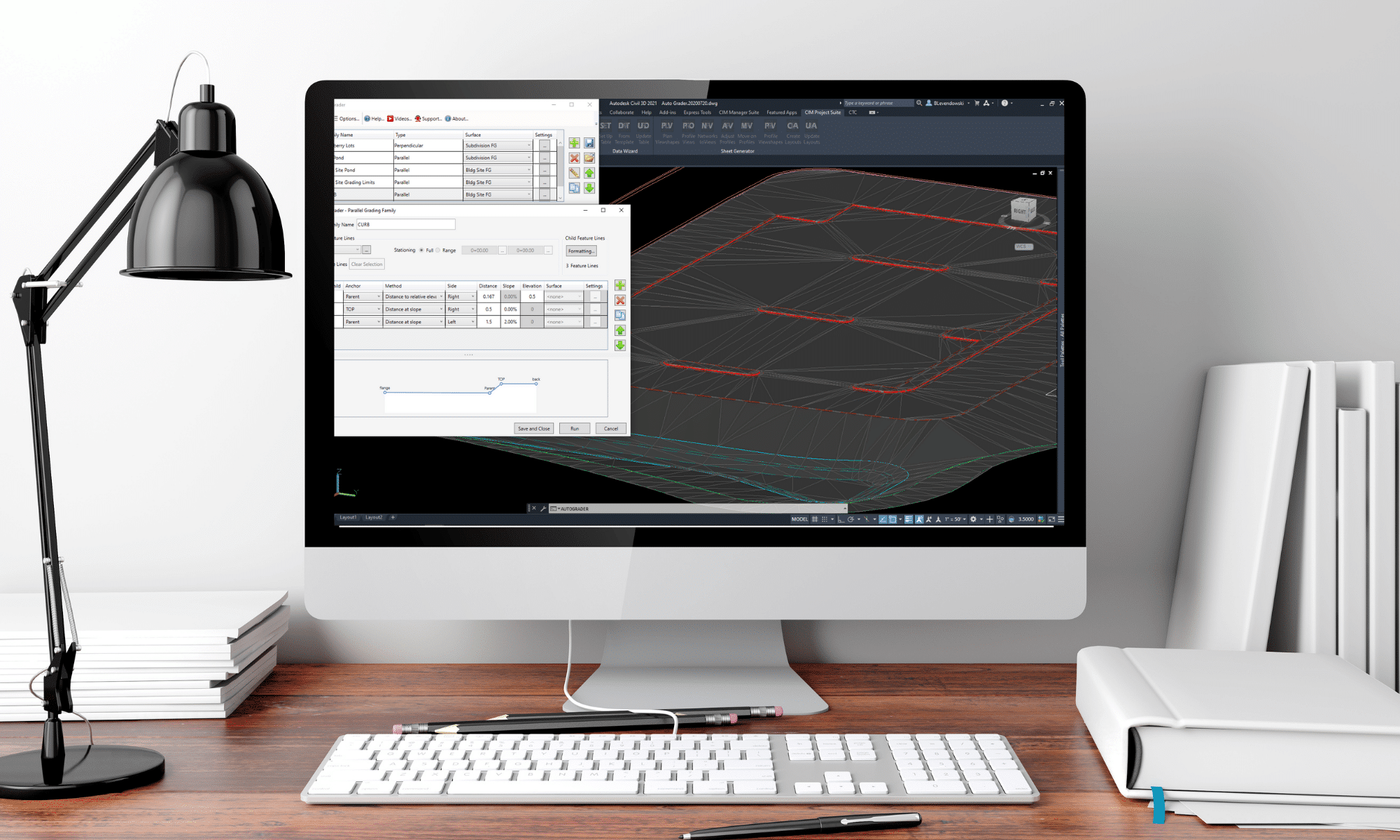
    And if that isn’t powerful enough for you, consider using CTC Software’s Auto Grader to automate the rest of your grading! This tool dovetails beautifully with the native split point resolution for feature lines in sites.

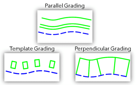
    Auto Grader has 3 different types of “Grading Families” that can be used to tackle almost any grading project.

    Parallel Grading allows mass dynamic stepped offsets from one or multiple baseline feature lines. Offering flexible grading for project areas such as curbs or ponds

    Perpendicular Grading allows mass insertion of elevation points/grade breaks across feature lines connecting to a baseline feature line. Offering automated grading solutions for lots in a subdivision or drop curbs.

    Template Grading is the newest addition to this tool allowing incredibly flexible 3D insertion control over template feature lines. Allowing you to establish grades from baseline feature lines and associate relative grades to the inserted template. This offers unparalleled flexibility for operations such as building envelope insertion.

    Hopefully, this challenges you to find even more efficiencies in your use of feature lines.

    How a CMMS System Can Increase your Business’s ROI and Uptime

    Have you been tasked to minimize your equipment downtime, increase asset condition visibility and spare parts?  If so, this can be a daunting task for an asset–heavy organization to move to a more proactive maintenance routine without the proper tools. 

    A Computerized Maintenance Management System (CMMS) can accomplish this goal through the following tools: 

    • Increased team collaboration via application based commenting system 
    • Accurate reports to help you plan and optimize maintenance plans and parts availability 
    • A single source of truth will allow a business to avoid duplicate work orders 

    In the recent 2020 Benchmarks & Best Practices for Maintenance Management Report, facilities using an effective CMMS have reported seeing 88% cost savings ranging from tens of thousands to millions of dollars. 


    4 ways a CMMS can improve your business: 

    1. Reduce Equipment Downtime 

    Lowering equipment downtime is a common objective in any asset-heavy organization. Typically manufacturers experience an average of 800 hours of unplanned downtime annually. These incidents can take a heavy toll and result in an average cost of $17,000. In some industries, downtime can have a massive impact, costing your business $50,000 per minute, which translates to $3 million per hour. 

     Equipment failure, human error, and low visibility into asset conditions are some of the reasons for these incidents. With a CMMS solution, you can avoid these unplanned downtimes by replacing physical paperwork and application silos by introducing a single source of truth to track: 

    • Workflow and work orders 
    • Asset and physical equipment conditions 
    • Accurate supplies counts (parts, materials, etc.)
    • Service schedules and invoicing 

    Having instant access to this data can help you build more proactive maintenance plans for your assets and equipment. Enhanced reporting on these metrics will allow your team to analyze failures and, in turn, minimize future incidents. 


    2. Maximize Labour Force Efficiency 

    Maintenance managers need direct access to PM plans, asset documentation, and part supply info. Without this information, issues can arise, such as duplicate work orders and increased overtime costs.  These are the hallmarks of a reactive maintenance cycle vs. a proactive approach. With the proper CMMS tools, a technician will gain insight into the following: 

    • Create, evaluate, prioritize, delegate, and monitor work orders from any system by managers and operators. When a work order is done, they will also receive up-to-the-minute updates. 
    • When there is a new job order, technicians will be notified immediately, and valuable information such as repair histories, checklists, asset manuals are easily accessible. 
    • Users can plan proactive maintenance by setting up triggers for time, use, or condition-based maintenance. 
    • Technicians can add notes immediately onsite, mark a job as complete, and let others know a specific asset’s status. 

    With all this data readily available, maintenance managers can make more informed choices regarding labor costs and efficiency. Creating a comprehensive preventive maintenance plan becomes a reality with a CMMS system, which saves your organization downtime and lowers costs. 


    3. Extend the Life of your Assets and Raise Their Reliability 

    To improve the efficiency and reliability of maintenance operations, creating a preventive maintenance plan is necessary. Predictive analytics yield a tenfold return on investment, according to one study, and results in savings of 30 percent to 40 percent. Organizations that configure the bulk of their Assets in a CMMS report significant improvements in equipment reliability. 

    A CMMS system places all of your PM dashboards and data in one place. Because of this, maintenance planners see the big picture and improve their KPIs via the following tools: 

    • Generation of custom reports on asset downtime and costs to improve maintenance plan 
    • Quick access to all related Asset documentation such as work order history, required safety equipment, and failure codes 
    • Real–time tracking of metrics (e.g., mileage, gauge readings, and operational hours) 
    • Integration with other systems for business-wide collaboration 

    All this functionality in your hands will lead to the automation of maintenance plans and insight into improvement areas. 


     4. Upgrade your Inventory Management Tools 

    Maintaining your MRO stock (maintenance, repair, and operating supply) is essential for reducing downtime. Your technicians need to be able to order parts easily to complete repairs on time. MRO supply can be costly. In many cases, MRO accounts can make up as much as 40% of a business‘s annual procurement budget. 

    A modern CMMS tool can assist with inventory management, save time on repairs and reduce duplicate orders by: 

    • Providing real–time tracking of spare parts and all relevant data (i.e., purchase date, availability, and locations where the part is stored) 
    • Automating purchases of parts to avoid extending downtime on repairs 
    • Reporting on inventory costs, order history, and usage metrics 
    • Notifications sent to Technicians of which parts are required  

    Implementing a CMMS solution can have an immediate positive impact on your equipment uptime and increase your ROI. Moving away from reactive maintenance will result in fewer equipment malfunctions and raise efficiency across the organization. 

    To learn more about the Meridian CMMS solution and how they can help your team, please contact the SolidCAD Meridian team.  

    11 Revu Tools to Ease the Punch Walk Process

    This article was originally published by Troy DeGroot and Bluebeam, Inc. on the Bluebeam Blog.

    Today I want to talk about Punch Walks, QA/QC, or whatever you might call it when you collect field data during or after construction.

    I started my career detailing structural steel. As a result, I was often required to juggle large plan rolls, tape measures, pens, and a level to measure existing conditions.

    These measurements would then be brought back to the office to make sure the railings and stairs fit perfectly when fabricated. Obviously, this was before emerging technologies like building information modeling (BIM) and laser scanning.

    So, how has Bluebeam Revu improved field data documentation?

    Here are 11 of my favorite Revu tools that ease field data collection and distribution.

    Standardizing plan symbology will replace long, written notes—increasing consistency, legibility and speed. These symbols are manually created ahead of time or on the fly. To save the most time, I suggest building your symbol list in Microsoft Excel. Importing the CSV file automatically generates large lists of symbols, along with the associated comment.

    Embed images, 360-degree images, or even videos with audio giving a clear description of the field conditions. The Flipbook is a clean way to add many images directly where they apply on the plan rather than off to the side someplace with a reference number.

    Create a template PDF form to quickly fill in the information needed. Before I save the template, I like to add a blank page after the form. This provides a place to drop a related image or Snapshot from a plan or detail, including clouds and other markups. Save this to your template folder for quick access every time.

    Speaking of the Snapshot, quickly grab a screenshot of the affected area of the drawing, saving it directly to the Clipboard. Paste this image on your RFI form, in a written report, or directly into an email. Your markups will come over, assuring the form matches exactly what’s on the large plan.

    Use Studio Projects to keep data organized and available to all stakeholders. A Digital Dashboard is a great way to organize everything in a visual format, similar to a website.

    Before each site walk, create a layer naming it with the date, then set it to Current. This will record all the markups on an isolated layer. Turning layers on and off allows you to track inspection progress.

    Create Spaces to track where on the plan your markups are located. If you walk into a room on-site and want to know all the information associated with that room, simply sort your markups List by Spaces.

    Create custom Columns to track individuals or maybe subcontractors who are “Responsible” for changes or fixes.

    Create custom Statuses to track progress on your projects, whether you use them to mark things complete for yourself internally or the general contractor who owns the documents. Changing a Status will automatically stamp the time, date and author. These status updates cannot be edited or removed by anyone.

    A custom Legend is a great way to represent the Markups List visually directly on the sheet. This could include a description of the symbol or even the number of times it was placed.

    Finally, Summary Reports are extremely powerful using Bluebeam Revu. Creating a PDF Summary report of all the markups on the drawing can be a clean and easy way to transfer information to others on the team. This is especially true when including a Capture Media Summary, which will embed all the images into the document.

    You may be using some of these tips already. I hope you learned a few more to streamline and improve the quality of your Punch Walks, QA/QC or whatever you might call it when you collect field data during or after construction.

    If you like these tips and want to see the technical steps, check out my YouTube playlist from last summer.

    Flexible, Customized Legends and QTOs with CTC’s Data Wizard.

    Flexible, Customized Legends and QTOs with CTC’s Data Wizard.


    How do you tackle quantity takeoffs in your projects? Do you use Civil 3D’s QTO Manager? Do you scale on paper or PDF’s?

    Between the inaccuracy of paper and PDF calculations, and the tedious setup and inflexibility of the MTO Manager, we don’t have a great solution for quantities of what’s in our projects.

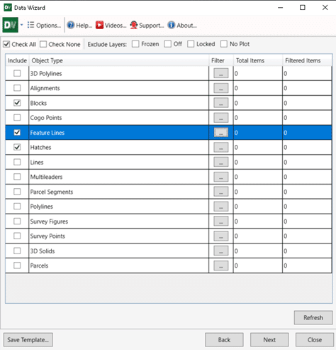
    Data Wizard can make this cumbersome task a lot more efficient and accurate. This tool searches your drawing for Civil 3D & ACAD point, line, and area type objects then tabulates them all for you.


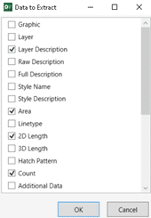
    This is a very versatile tool, and once objects are selected and filtered, we can choose specific data to extract. In the case of QTO, a layer description can be used to label the item. Then areas, lengths, and counts can be tabulated for each respective item.


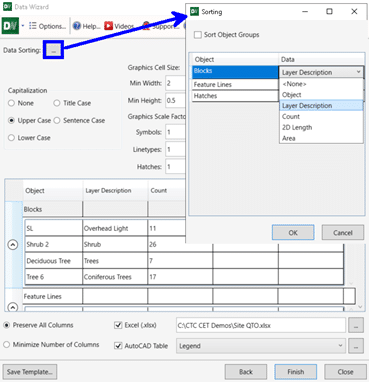
    We can then sort and prep this data for AutoCAD Table insertion, or export to Excel. Data Wizard allows you to customize what you are looking for every step of the way!


    Once the QTO is set up, we can also save the setup to a template to share among projects. This speeds up the QTO process even more for future projects.
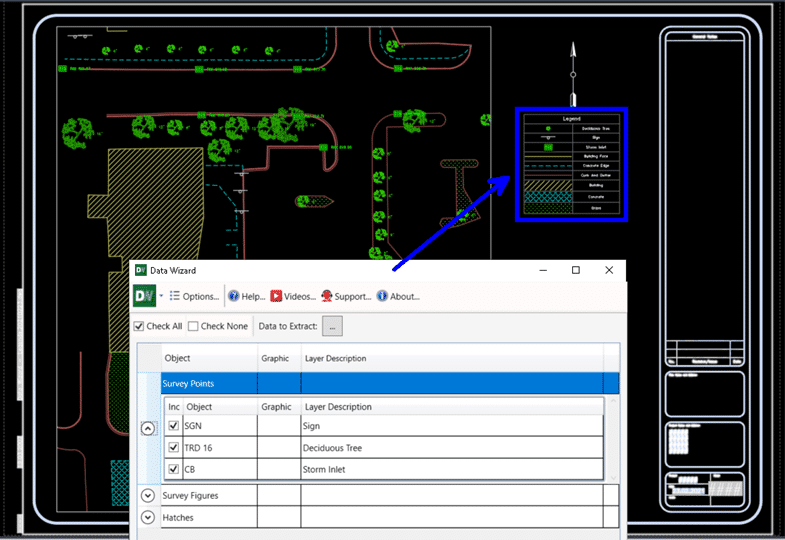
     

    This is just one way to use Data Wizard. Alternatively, we can extract graphics and layer descriptions to produce sheet-specific legends for our plan production.


    This tool will save time and reduce human error with any tabulation tasks across your projects!

    Automated, Flexible, and Iterative Plan Production Tools. CTC’s Sheet Generator Workflow is the Whole Package.

    You can’t afford to create plan and profile sheets without these tools!

    If you have ever tried to create Plan & Profile sheets on mass with the Native View Frame tools it sure beats doing it by hand. But it also still requires a lot of manual manipulation after the layouts are created. And worst of all, you have to get it right the first time because the tools were not built to offer an iterative workflow.

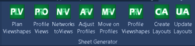
    CIM Project Suite’s Sheet Generator workflow is a set of tools to speed up and increase the flexibility of the sheet creation process.

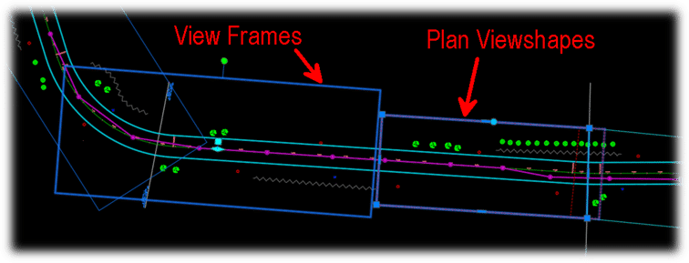
    Native View Frames vs. CTC Software’s Plan Viewshapes

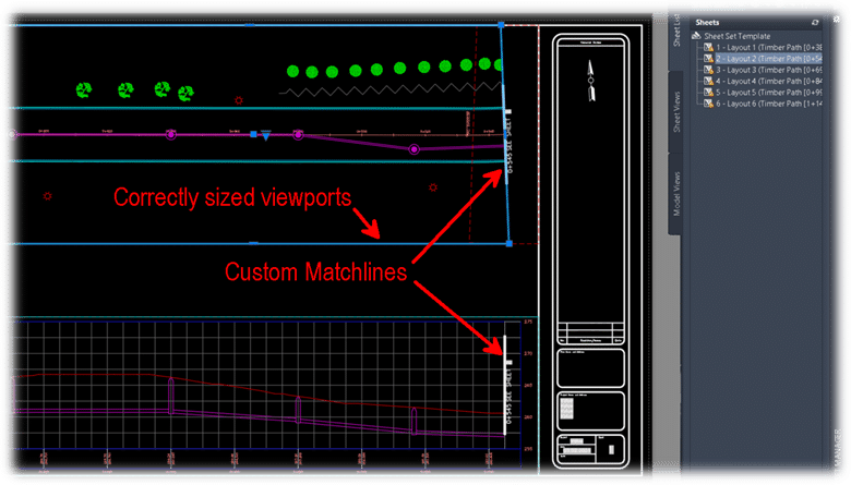
    Plan Viewshapes consist of a block to represent the extent of your allowable viewport area in a sheet and a polygon to represent the actual shape and positioning of the viewport you would like to create. No more chopping View Frames at matchlines and hatching the rest of the rectangular area in your sheets.

    Creating profile views natively vs. with CTC’s CIM Project Suite.

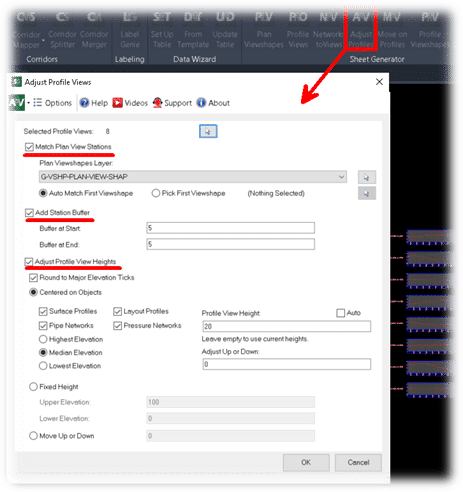
    This is a bit of a trick comparison because the Sheet Generator workflow takes advantage of the native tools for creating profile views. Although, Sheet Generator offers much more mass editing controls for profile view heights, stationing, and object projection. These tools give you the ability to have uniformity across any number of profile views, and have lots of flexible options for centering these profile views on key information.

    The sheets that are created from CTC’s workflow will pull from company templates for sheet layout, and integrate into Sheet Sets seamlessly. The previously specified Plan Viewshapes and Profile Viewshapes create polygonal viewports with custom matchline blocks. The layout creation also adds north arrows, names layouts, and adds sheets to sheet sets automatically.

    The most important part of this workflow is that if the linear design changes in any way, all the sheets can be updated. Not recreated but updated! This means that custom notes and legends, details and blowups will all stay in the layouts. Updates to viewports, north arrows, stationing, matchlines, layout names, and sheet set information all take place automatically when the layouts need to incorporate a design change. This iterative flexibility is a game changer for large projects, it eliminating human error, and executing massive changes to sheets with just a few clicks.

    I hope the Sheet Generator workflow peaks your interest and helps you to find a new level of intuitive automation for your projects.

    CTC also has great tutorials for all their tools on their Youtube Channel.

    https://www.youtube.com/watch?v=_IlLnoK1qrk&list=PLTCH_HgPsbw_DWqEaVLF9xhWMjGPey9SI

    Create Your Own AutoCAD Tutorial Library

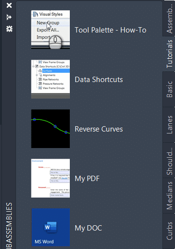
    Are you or do you have a staff member in your office who likes to create tutorial content?  Or maybe you simply have some web links to which you’d like to regularly refer.  Maybe you’d like to share these tutorials with the rest of your AutoCAD team.  Sure you can tell them where the videos, documents, or web links are, but the users must open them outside of the AutoCAD environment.

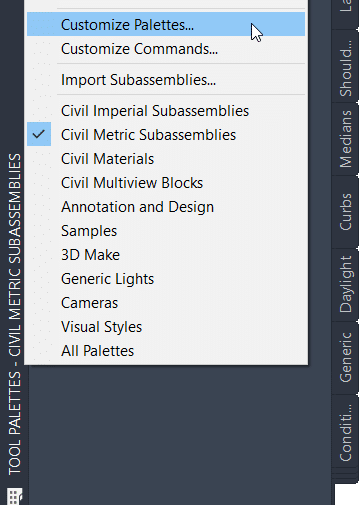
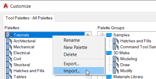
    What if the users could access this content right within AutoCAD?  The closer the help is to the user, the better, I always say.  Consider creating a custom tool palette containing buttons to open these tutorials, and sharing it with the users.

    I’ll go on the assumption you already know how to create and share a tool palette.  I’ll show you how to create tools that link to files or web links.

    Create the Tool

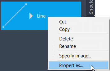
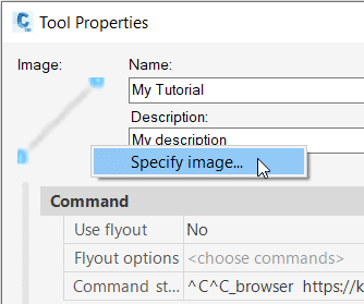
    Drag a line or a text object to your new tool palette then edit its properties.

    Web Link

    Edit 5 properties:

    • Name.
    • Description.
    • Specify Image.
    • Turn off the flyout option
    • Edit the Command String.  Enter this information ^C^C_browser https://WebLink  Paste the link after browser.

    File

    The only difference between this tool and the web link is the Command string which uses a little LISP code.  Enter the path to your file after findfile, within the quotes.  DO NOT use back slashes, only forward slashes.

    • ^C^C (startapp “explorer.exe” (findfile “C:/temp/1.docx”))

    That’s it.  Make it easy for your users to get the help they need!


    How a Localized, Multi-Language CMMS Can Streamline Global Operations

    Any sizeable global corporation that maintains sites worldwide knows how language barriers can negatively impact communication and team productivity. 

    Let’s break this down: If person-to-person communication is difficult, adding a complex tool such as a computerized maintenance management system (CMMS) will only exasperate the situation. Many modern CMMS tools are English only, which further hinders an international business’s efficiency. 

    Today’s Covid-19 reality adds another layer to this, with most of the workforce working remotely. Due to these challenges, many global corporations have begun rolling out localized or multi-language tools, including CMMS. 

    Key Asset Management Issues Businesses That Lower Efficiency 
    • Not focusing on high-priority maintenance jobs 
    • A lack of proactive maintenance leads to safety issues and unplanned downtime 
    • Communication breakdown between teams that causes delays 
    • Spare parts inventory shortage due to incomplete stock tracking tools 

    If you add language barriers to the mix for multi-site CMMS users, this adds increased challenges: 

    • Incomplete international data due to English only tools 
    • Training issues lead to a lowered understanding of the CMMS capabilities 
    • On–site technicians having issues completing work because they can’t easily access critical information 
    • Smaller tool user base due to language barriers 

    All these issues can have a substantial negative impact on efficiency and team communication. The accuracy of mission–critical asset data can drop, which leads to increased unplanned downtime. 

    How A Localized CMMS Application Can Help Your Global Business 

    A CMMS tool with the ability to localize to your region will provide the ability to translate specific language, cultural and numerical requirements to a more familiar format. These can affect the following: 

    • Language 
    • Dialect (i.e., Quebec vs. France) 
    • Legal requirements 
    • Numeric, date, and time formats 
    • Currency 

    A Localized CMMS will remove layer of communication issues that will increase data completeness and clarity and ease access. 

    4 Benefits of a Localized, Multi-site CMMS Tool 
    1. Modern User Interface 

    A complicated legacy CMMS interface can be tough to navigate and cause frustration due to: 

    • Unclear levels of user rights and privileges 
    • Unintuitive navigation of workflows 
    • Ineffective user training sessions 

    These factors can lead to lower user adoption of the tool and will negatively impact the business. 

    An easy-to-use modern CMMS will alleviate these issues as training sessions become more effective and increase user adoption. 

    2. Native Multi-Language Support 

    Current CMMS platforms are typically only available in English or provide a reduced set of localization capabilities. 

    A powerful multi-site CMMS like Accruent’s Maintenance Connection provides multi-language and does it with a single database.  Users can enter data efficiently using their local language into a single source of truth.  Everyone using the platform is accessing the same data, leading to increased accuracy of data with no need to sync to different environments.  

    3. Mobile and Remote Access for Today’s Reality 

    This year will highlight the need for all of your tools to offer Remote and Mobile access. This is further confirmed by a 2017 ARC Advisory Group global report indicated that 50% of technicians use a mobile device for work orders, and this number is only growing. 

    On–site Technicians that have to rely on wi-fi and laptops will lead to delays in communication and reduced quality of data. 

    This is why an international business needs a CMMS tool with full mobile access. 

    A fully localized mobile application will allow on-site technicians to improve their efficiency and quality of work by helping them: 

    • Find mission–critical asset documentation quickly 
    • Process work orders remotely and in real-time 
    • Order parts in the field to reduce delays and confirm parts availability 
    • See the entire Asset maintenance history 
    • Provide immediate changes to work order status 

    They can accomplish all this in their local language, enabling a smoother maintenance experience with increased effectiveness. In a recent US-based survey conducted by Maintenance Connection, one customer estimated they had saved $1 million due to this kind of mobile CMMS implementation. 

    4. A CMMS Tool That Spans Multiple Sites and Regions 

    CMMS suites that only allow for a single site with limited integrations lead to unstandardized data silos that can cause discrepancies and slow down team interactions. 

    If your CMMS tool can handle multiple sites, the user base pulls data from a single source of truth quickly and accurately. Access to these documents can be controlled effortlessly via centralized permissions for improved security. 

    A modern multi-site and multi-national CMMS will provide these benefits: 

    • Centralized data  
    • Global reporting tools 
    • Standardization of data by removing the need for information silos 
    • Increased data security and safety 
    • Real–time status of work orders across the globe 
    • Full integration for engineering document management tools such as Accruent’s Meridian 

    Features like this can reduce data input errors, standardize workflows, and make for easy user privilege administration in a centralized environment. 

    To learn more about Meridian solutions and how they can help your team, please contact the SolidCAD Meridian team.  

    A Document Management Workflow for the Modern Construction Project

    This story was originally published by Bluebeam, Inc. on Built, the Bluebeam Blog.

    Most construction projects are massive undertakings. Teams of architects and engineers work tirelessly preparing large volumes of design documents before they ultimately make their way onto a construction jobsite, where workers labor vigorously to build off those plans down to the tiniest details.

    The evolution of technology in the construction industry has made the arduous task of managing the flow of such large project document loads easier. Once initial plans are made, multiple rounds of revisions must take place among varying project stakeholders before they’re ultimately pushed out to the field, where more revisions may occur as new challenges emerge.

    Pablo Giraldo, an assistant construction technology manager with The Walsh Group in Atlanta, Georgia, is one among a crowd of passionate and tech-savvy construction professionals who have embraced digital transformation in the industry. Giraldo has spent a lot of time, including through his own growing YouTube channel, figuring out how to make digital transformation of document management work on his projects.

    Here is a breakdown of how Giraldo leads document management using the varying tools within Bluebeam Revu, based on his recent presentation as part of Bluebeam’s ongoing virtual events series.

    Create Sets

    The first thing Giraldo does to initiate his document management workflow is to create document Sets in Revu.

    Sets allow Revu users to open a collection of plan documents as if they were a single file. Pages in a Set are organized in a specific and sorted order, including any revisions. Sets ultimately allow users to navigate through multiple files in Revu as if they were one document.

    Publishing the latest Set ultimately allows files to load faster for workers in the field; it also allows a check-out/check-in system that allows users to check-in/out a document one person at a time.

    https://youtu.be/XOmzLYnW3gk 

    Batch Link

    Next, Giraldo Batch Links his Set. Batch Link in Revu automatically creates navigational hyperlinks within a particular group of documents based on user-defined criteria. Batch Link, which is only available in the eXtreme edition of Revu, can be run against multiple PDFs or a single, multi-paged PDF.

    “This is beneficial as you’re going through the drawings to easily flip back and forth through different documents,” Giraldo said.

    This is particularly helpful for workers in the field, Giraldo said, as they can transition between different documents on their iPads, looking at different sections of drawings as they spot important details while working on the jobsite.

    Hyperlink drawings

    In addition to Batch Linking document Sets, Giraldo often uses hyperlinks throughout different documents in other ways to help provide field workers and other collaborators with easy ways to find and reference critical project information as they work.

    Links, which can be placed on anything in a PDF, including markups, can include anything from linking to other project documents to reference websites to any other important, web-accessible information.

    https://youtu.be/gjRN4JM03ms 

    Publish

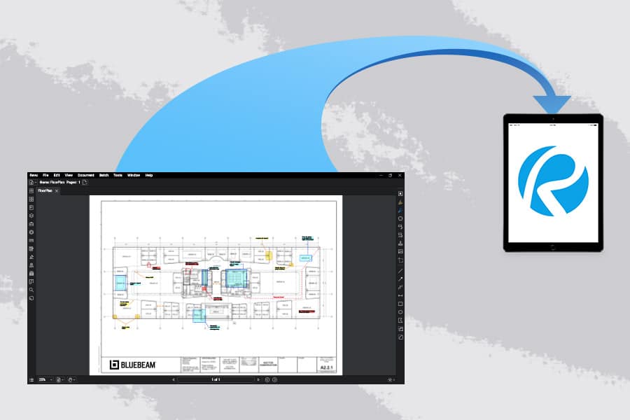
    Once Giraldo has set up all his Sets, Batched Linked and set up hyperlinks to other documents or resources throughout the documents, now it’s time to publish the Sets and send them out to workers in the field. There, workers will use the Bluebeam app on iPads to sync to the latest document Sets to reference and work off while in the field.

    Anytime a worker in the field can connect to the internet, either via WiFi or cellular connectivity, they can hit “Sync” in the Bluebeam app. Then all the documents will automatically download the latest set of drawings, Giraldo said.

    Create dashboard

    One of the powerful ways to help everyone collaborating on documents—whether they’re in-office engineers approving plans or field workers implementing them—is to create a digital project dashboard in Revu. Digital dashboards are hyperlinked, button-enabled PDFs that can be configured and designed such that users have a simple place for reference for all project documents and resources, alleviating the need for anyone to have to navigate through complex folder structures to find documents.

    Giraldo said once he’s completed the above steps, he ultimately creates two project dashboards: one for workers who interact with documents in the office, and another for workers in the field. The dashboard for workers in the office is slightly more robust, with multiple buttons directing workers to key documents and resources. The dashboard for field workers is less detailed, allowing them a simple and easy-to-understand interface as they need to review documents while working on hectic jobsites.

    https://youtu.be/knTzovEw5Fs?list=PLJ7Sea2rdFrlbonLl3F3u3-w35nkIXLdh

    Create Studio groups

    Studio, which provides users with document management and real-time collaboration capabilities, is another tool Giraldo uses on his projects. Creating groups within Studio allows the administrator—in this case Giraldo—the ability to provide different users access to different documents within the Studio Project as well as the ability to collaborate on document review in Studio Sessions.

    Users can have three levels of permissions within Studio: read, read/write and read/write/delete. “This can function as your server,” Giraldo said of Studio Projects, although most larger firms ultimately store their files elsewhere. “I’ve seen small companies rely on Studio Projects entirely for their document management.”

    Bluebeam for iPad

    A major asset for Giraldo’s document management implementation with his projects has been use of iPad in the field. The Revu for iPad app, in addition to giving field workers access to view project documents nearly like an in-office worker would on a desktop computer, is especially great when it comes to project tracking, Giraldo said.

    Moreover, Giraldo has used tablets in the field to take pictures of completed work to store in the document, such that workers can view project elements as they’re installed within the drawings as construction progresses. Giraldo has also taken to dictating notes using the audio recording capability within the iPad app to make notes on certain markups within drawings while out in the field.

    Track work with statuses

    Lastly, the Markups List in Revu includes a Status column that allows Giraldo and other users the ability to track the progress of different project elements. What’s more, the status column is followed by a color column that allows users to color-code different statuses.

    Giraldo on a recent project, for instance, had three different statuses displaying what stage a series of pre-cast panels were at: ordered, delivered, installed. To set a status, users can right click on a markup, click “Set a Status,” then pick the project element. This can be done both in the field on a tablet and in an office on a desktop.

    Streamlined efficiency

    Overall, this digital document management workflow has helped Giraldo and the rest of his project team cut down on printing and use of paper documents, which often led to confusion and disorganization on jobsites. It has also helped field workers be more efficient, Giraldo said, as they no longer must account for and reference rolls of paper documents.

    Thanks to these tools provided by Revu, as well as construction professionals like Giraldo who are willing to figure out the connective elements of establishing a fully functional digital document workflow, construction workers have an example of how to store, organize, track and find important project documents and resources digitally, making the office-to-field document flow easier to manage.