• CIM Project Suite 22.0.3 Released

    We are pleased to announce that our partner CTC Software released Civil 3D CIM Project Suite, version 22.0.3. It is now released and can be accessed on the CTC website.

    Below are release notes:

    22.0.3 9/17/2021 CIM Project Suite Auto Grader Bug Fix Fixed an issue where “split points” in parent feature lines were causing an error. Fixed an issue where creating parallel child lines with a specified station range caused unexpected results. Fixed an issue where inward and outward offsetting was giving unexpected results. Fixed an issue where perpendicular child feature lines were not creating at the user-defined station values. Misc. user interface improvements.
    22.0.3 9/17/2021 CIM Project Suite Corridor Mapper Bug Fix Fixed an issue where corridors with disabled regions were causing the app to fail. Fixed an issue in how the app dealt with corridors containing previously mapped targets.
    22.0.3 9/17/2021 CIM Project Suite Corridor Splitter New Features Added interactive region selection and graphical highlighting, providing a much more intuitive app workflow.
    22.0.3 9/17/2021 CIM Project Suite Earthwork Processor Bug Fix Fixed an issue where the region offset command would not work on very small region objects.
    22.0.3 9/17/2021 CIM Project Suite Label Genie Bug Fix Fixed an issue where pipe networks could no longer be labelled.
    22.0.3 9/17/2021 CIM Project Suite Pipe Planner Bug Fix Fixed an issue where part elevations were not updating in the app after applying changes to the drawing. Fixed an issue where part elevations were not updating when importing external spreadsheets. Fixed an issue where pipe lengths for the pipe depth at interval property were not calculating correctly. Fixed an issue where parts of the same name, but in different pipe networks, were not allowed by the app. Fixed an issue where the structure rotation angle was incorrectly rounding.

    15 time-saving labeling shortcuts with CTC’s Label Genie (Part 1)

    Label Genie can save you a ton of time by creating all sorts of useful labels quickly. Here’s 15 examples that you can use right now.

    Descriptions of the settings are included, but to really get up and running quickly Label Genie template files and the sample DWGs have been made available as well. Simply copy the .lg files into %AppData%\CTC\Label Genie then open up Label Genie. They will then show up in the dropdown box in the Label Genie template section.

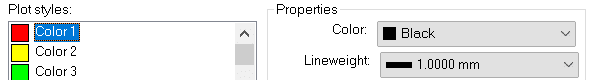
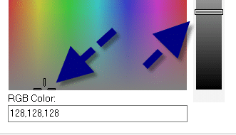
    If the labels you are creating are for design purposes, you may want to set their layers to a non-plotting style that you can ignore, or a layer that you can just freeze without affecting others.

    Labelling for Corridor Design (*Corridor Design.dwg)

    1.      Label Assemblies (*Assembly Name.lg)

    Make it easier to which assembly is which at a glance by label their names. The labelling is done with a field, so that if the assembly name changes, a simple regen will update the label.

    • Type = Multiline Text
    • Anchor Object = Assemblies (Layer filter = *)
    • Formatting, contents = (Assemblies).(Name)
    • Formatting, Y offset = -4

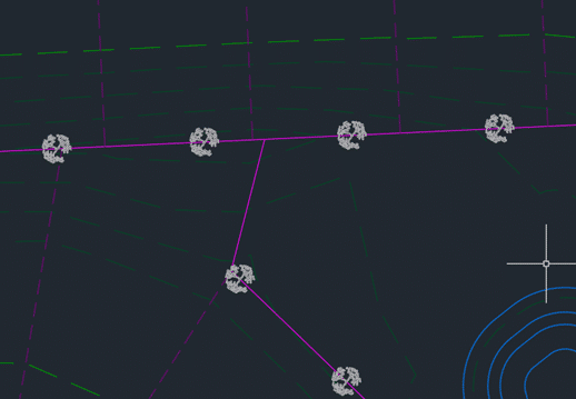
    2.      Label Alignment Names (*Alignment Name.lg)

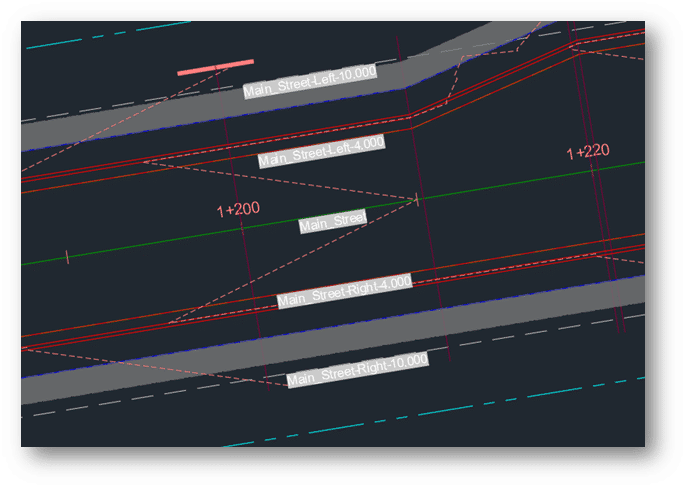
    When doing corridor work, we may want to see alignment names at a glance. This is especially true if setting up a lot of labels with the Corridor Mapper, for instance. Label the alignment names at regular intervals, oriented with the lines to avoid having to check the property palette constantly.

    • Label Type = Multiline Text
    • Anchor Object = Alignments (Layer filter = *)
    • Anchor Point = Vertices (Interval = 100, rest unchecked)
    • Formatting, contents = (Alignments).(Name)
    • Formatting, orientation = To Objects
    • Formatting, Y Offset = -0.5

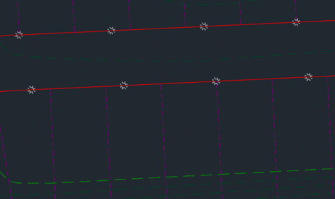
    3.      Label Feature Line and Polyline Layers (*Feature Line Layer.lg / Polyline Layer.lg)

    Continuing the theme of adding some labels to corridor target objects, we can label feature line (and polylines) layer names at intervals. For feature lines, you may want to switch the Contents to the feature line’s name instead of the layer name – depending on how you like to use feature lines.

    • Label Type = Multiline Text
    • Anchor Object = Feature Lines (Layer filter = *)
    • Anchor Point = Vertices (Interval = 100, rest unchecked)
    • Formatting, contents = (Feature Lines).(Layer)
    • Formatting, orientation = To Objects
    • Formatting, Y Offset = -0.5

    If you have a lot of polylines for use for horizontal target condition subassemblies, you can label those as well, to make it easier to see what layer names they have. They tend to be shorter, so instead of intervals, midpoints might be more appropriate.

    • Label Type = Multiline Text
    • Anchor Object = Feature Lines (Layer filter = *)
    • Anchor Point = Vertices (Interval = 100, rest unchecked)
    • Formatting, contents = (Feature Lines).(Layer)
    • Formatting, orientation = To Objects
    • Formatting, Y Offset = -0.5

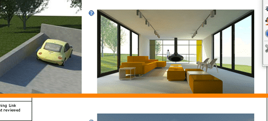
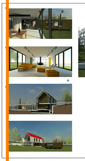
    Labelling for Presentation (*Presentation.dwg)

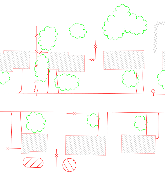
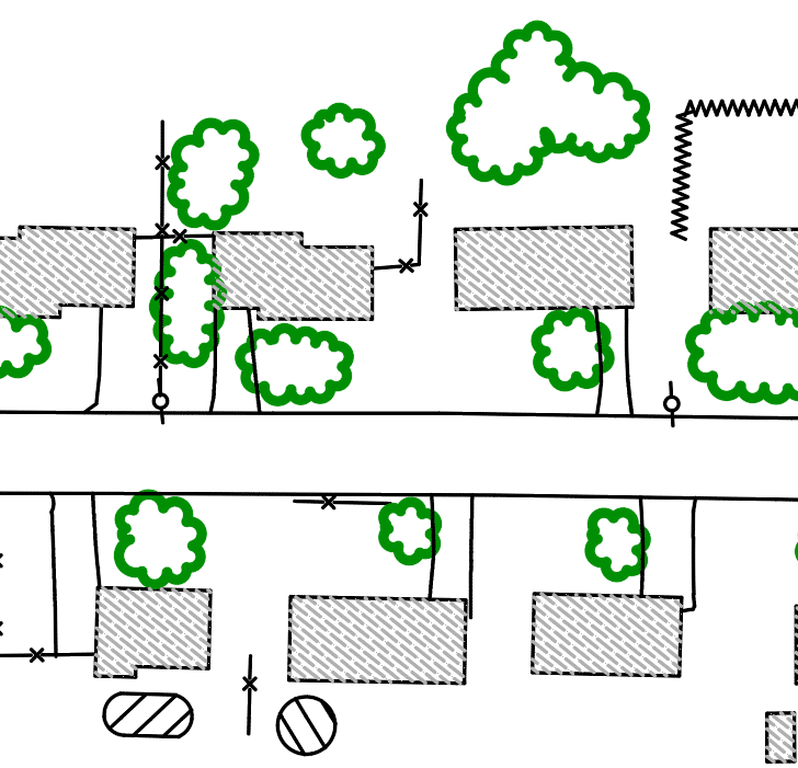
    Sometimes, we need to fill in some objects in the drawing for conceptual presentation. At the conceptual stage, we can forego precise placement and mass populate objects such as trees, lights, and structures quickly. These objects, in turn, can be exported to InfraWorks for even greater visual impact.

    4.      Place Tree Blocks at Back of Lots (*Place Trees.lg)

    First, we can place some trees at an interval at the back lot line.

    • Label Type = Blocks
    • Anchor Object = Feature lines (Layer filter = _LOTS BACK, C-PROP-BNDY)
    • Vertices = Interval 60
    • Format, Block Definition = Deciduous Tree
    • Format, Scale = 60

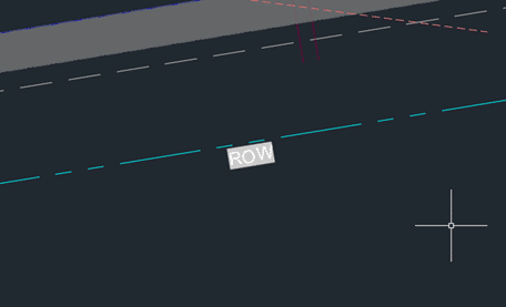
    5.      Place Lights (*Place Lights.lg)

    Lights are place along the right of way with an offset at intervals.

    • Label Type = Blocks
    • Anchor Object = Feature Lines (Filter = *ROW*)
    • Anchor Point = Vertices (Interval 100)
    • Formatting, Block Definition = SL
    • Formatting, Scale = 30


    6.      Place Building Footprints (*Place House.lg)

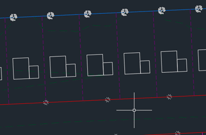
    Next, we can place some house block representing structure footprints in lots.

    • Label Type = Blocks
    • Anchor Object = manually select a row of side lot lines at the North end of subdivision
    • Anchor Point = Vertices (Begin of Object)
    • Formatting, Block Definition = House
    • Formatting, Scale = 0.8
    • Formatting, Orientation = To Object
    • Formatting, Rotation/X Offset/Y Offset = 270 / 40 / 30

    Measuring and Quantifying (*Measure and Quantify.dwg)

    7.      Dimension a Building (*Dimension Building.lg)

    We can automatically apply dimensions to objects using the Label Genie. Let’s try it on a building footprint.

    • Label Type = Dimensions
    • Anchor Object = Polylines (Layer filter = A-BLDG)
    • Anchor Point: Segments
    • Formatting, style = Annotative
    • Formatting, annotative = checked on
    • Formatting, Orientation = To Object
    • Formatting, Rotation / X Offset / Y Offset = 0 / 0 / -8

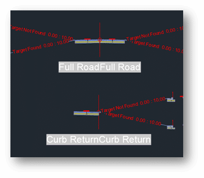
    8.      Dimension Curb (*Dimension Curb.dwg)

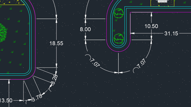
    We can dimension curb feature lines as well. Key to success is consistent stationing direction – always counter-clockwise or clockwise.

    • Label type: dimensions
    • Anchor object: feature lines (Layer filter = C-PRAVE-CURB-EOA)
    • Anchor point: segments
    • Formatting, style = annotative
    • Formatting, orientation = to object
    • Formatting, rotation / x offset / y offset = 0 / 0 / -8

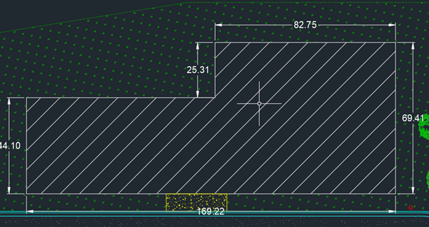
    9.      Measure Areas (*measure areas.lg)

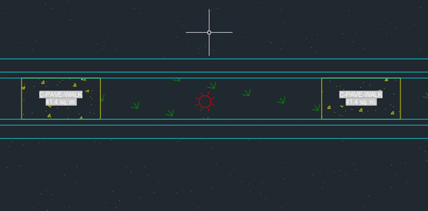
    Next, we generate area quantity labels for various hatching in the drawing. Note that labels are created in the centroids of hatches. This means that if you have an “L” shaped hatch, such as the grass in this drawing, the label may end up being outside the hatch. Some manual repositioning may be required.

    • Label Type = MultilineText
    • Anchor Object = Hatches (layer filter = *)
    • Anchor Point = Centroid
    • View Type = Plan
    • Formatting contents =
      • (Hatches).(Layer)
      • <New Line>
      • (Hatches).(Area)
        • Field customization: Format = Decimal, Precision = 0.0, Suffix = sq. m.
      • Formatting, Style = Annotative
      • Formatting, display width = 12

    More Labelling Tips On the Way

    That concludes the first 9 of the 15 time-saving shortcuts using the CTC Label Genie. It can help us quickly generate labels that can help us find the design information we need, place blocks to flesh out a conceptual design drawing, and dimension and measure various objects.

    Keep an eye out for Part 2, where we cover locating points and objects, as well as communication key surface information.

    *Please email us at info@solidcad.ca to request the data sets.

    Autodesk Desktop Connector Update – February 13, 2023

    We are pleased to share with you the highlights of the latest Autodesk Desktop Connector update!

    New Feature and Enhancement:

    • Autodesk Construction Cloud drive now supports the View Online capability in Desktop Connector

    Resolved Issues

    • Users will experience faster performance when Opening DWG files that exist locally
    • Changes to how files are marked read-only which will significantly reduce occurrences of “File in use” category of errors
    • Improved messaging to provide better awareness when a file is opened if the file is locked by another user
    • Improved messaging in workflows which will result in files being sent to the recycle bin
    • When DWG files are opened from the Desktop Connector workspace, transient files (ex. bak, dwl, dwl2) will no longer be created
    • Desktop Connector will ignore activity initiated by Sophos anti-virus (SavService)

    For more information, visit here.


    Wrangle that Sheet: Making Revit Sheets Layout Easily with Free Tools from the BIM Project Suite

    The CTC BIM Project Suite is geared towards users doing the project work, the included tools aim to make everyday project work easier and more efficient that using Revit tools alone. There are 5 free tools accessed from the ribbon while working in Revit, as well as Revit Properties which is access from the File Explorer to allow you access to Revit file properties, such as the Revit version. The paid version of the Project Suite has an additional 13 tools to add to the Revit workflow. The 2022 release of CTC BIM Project Suite saw the addition of a new free tool, View Aligner.

    This tool allows you to select any view on a sheet and align the other views to it based on your project needs. The greatest advantage to the View Aligner tool is that it works across sheets.

    When selected from the tools on the ribbon the floating tool bar appears and can be repositioned to a convenient location.

    You have the option of 7 alignments, based on the crop boundary of the views. You can align by each edge; top, bottom, left or right, by either horizontal or vertical centerlines, or by levels.

    Upon selection of the desired alignment, instructions for ending the operation appear at the end of the toolbar.

    If you click back on the toolbar before pressing Esc you will need to click back into the view (so the toolbar goes white again) before you can press Esc to exit.


    Align Horizontally by Top Edge

    • Select the Align Horizontally by Top Edge icon.
    • Select the view with the position you want to align to.
    • Every view you click will now align horizontally top edge to top edge of the crop region.
    • Press Esc to complete the operation.

    To keep crop regions the same size for all plan views, use a scope box to control the edges.

    Align Horizontally by Centerline

    • Select the Align Horizontally by Centerline icon.
    • Select the view with the position you want to align to.
    • Every view you click will now align horizontally centerline to centerline of the crop region.
    • Press Esc to complete the operation.

    For details that don’t show the crop region try using centerlines to get the massing relatively aligned then adjust view names for a nice symmetrical look.

    Align Horizontally by Bottom Edge

    • Select the Align Horizontally by Bottom Edge icon.
    • Select the view with the position you want to align to.
    • Every view you click will now align horizontally bottom edge to bottom edge of the crop region.
    • Press Esc to complete the operation.

    Align the bottom of images to help determine the spacing for other elements on the sheet.


    Align Vertically by Left Edge

    • Select the Align Vertically by Left Edge icon.
    • Select the view with the position you want to align to.
    • Every view you click will now align Vertically left edge to left edge of the crop region.
    • Press Esc to complete the operation.

    Align images along the edge of a page for a nice crisp line.


    Align Vertically by Centerline

    • Select the Align Vertically by Centerline icon.
    • Select the view with the position you want to align to.
    • Every view you click will now align vertically centerline to centerline of the crop region.
    • Press Esc to complete the operation.

    Vertical alignment by centerline works best with the unrelated views that Revit can’t snap alignment to.


    Align Vertically by Right Edge

    • Select the Align Vertically by Right Edge icon.
    • Select the view with the position you want to align to.
    • Every view you click will now align Vertically right edge to right edge of the crop region.
    • Press Esc to complete the operation.

    Using a right edge alignment (or left) for elevations results in a cohesive look when grid bulbs for all views are aligned to the same side.


    Align By Levels

    • Select the Align by Levels icon.
    • Select the view with the position you want to align to.
    • Every view you click will now align by levels.
    • Press Esc to complete the operation.

    To use this alignment the scale of the views must be the same.


    TIPS:

    • Use the View Alignment tool to align ‘like’ items.
    • Assign a scope box to the crop regions to make alignment quicker.
    • Open each sheet you will be working on before starting the tool to use alignment across the sheets. You cannot access the project browser once the tool is active. Use the view tabs to flip between sheets to align the views horizontal across each sheet, then do the same to align vertically.

    • Alignment works best on views of the same type. As seen below when you align an image and a schedule the space between visible content and the outermost edge of the crop boundary are not the same so despite being aligned the appear “off”.

    Get your 2022 release of CTC BIM Project Suite and try the FREE View Aligner tool on your next project. Reach out to us at info@solidcad.ca

    Assign Point Layers by Note Column with Dynamo

    In this vlog, our Civil/Infrastructure Technical Product Specialist, Jae Kwon, will demonstrate how to assign point layers by Note Column with Dynamo application.

    Autodesk Dynamo is a programming environment that requires no programming experience. Dynamo enables designers to create visual logic so they can explore a wide range of parametric conceptual designs using logic, simple data and analysis without the need to create a physical prototype.

    This vlog will cover a demo of:

    • Problem to solve
    • No out of the box solution available
    • Dynamo script breakdown
    • Dynamo player, script run and result review


    Civil 3D 2022.0.1 CIM Suite Tools Updates from CTC

    We are excited to announce that our partner CTC Software released Civil 3D CIM Project and Manager Suites, version 22.0.1. It is now released and can be accessed on the CTC website.

    This update saw a lot of fixes and enhancements to new products released in 22.0.0 and before.

    Below are release notes:

    22.0.1 8/17/2021 CIM Project Suite Pipe Planner Bug Fix Fixed a variety of issues causing Pipe Planner to error out or crash. Improved application speed performance. Fixed issues with exporting to external spreadsheets. Fixed issues with importing external spreadsheets.
    22.0.1 8/17/2021 CIM Project Suite Pipe Planner Enhancement Added support for formulas in user-defined empty columns and rows. Added properties filter search bar. Added interactive selection of export starting cell. Improved part renaming, allowing old names to be reused on new part names within the same operation. Added new right-click options to edit the middle table. Misc. enhancements and performance improvements.
    22.0.1 8/17/2021 CIM Project Suite Pipe Designer Enhancement Improved part renaming, allowing old names to be reused on new part names within the same operation.
    22.0.1 8/17/2021 CIM Project Suite Label Genie Enhancement Added option to manually select anchor objects in drawings.  Added option when labeling layouts to create a unique layer for each layout.
    22.0.1 8/17/2021 CIM Project Suite Label Genie Bug Fix Fixed an issue where layout-specific labeling was not respecting exact viewport extents.  Fixed an issue where segment labels were not following the assigned layer. Fixed misc. issues with specific drawing files.
    22.0.1 8/17/2021 CIM Project Suite Earthwork Processer Bug Fix Fixed an issue where errors occurred if existing or proposed surfaces were empty or not overlapping one another.  Fixed an issue where earthwork region polylines that were significantly small would not offset and cause the app to error.
    22.0.1 8/17/2021 CIM Project Suite Data Wizard Bug Fix Fixed an issue where survey figures caused Data Wizard to error.
    22.0.1 8/17/2021 CIM Project Suite Parts Swapper Bug Fix Fixed an issue where parts not found in the parts catalog were causing Parts Swapper to file.
    22.0.1 8/17/2021 CIM Project Suite Corridor Mapper Bug Fix Fixed an issue where changes to assemblies would cause the app to error.
    22.0.1 8/17/2021 CIM Project Suite CIM Project Suite Bug Fix Fixed an issue where custom subassemblies were breaking when CIM Project Suite was installed.
    22.0.1 8/17/2021 CIM Manager Suite Template Tracker Bug Fix Fixed an issue where pressure network band styles were causing Template Tracker to error out.
    22.0.1 8/17/2021 CIM Manager Suite CIM Manager Suite Bug Fix Fixed an issue where custom subassemblies were breaking when CIM Manager Suite was installed.

    Civil 3D 2022 CIM Suite Tools Updates from CTC

    We are excited to announce that our partner CTC Software released Civil 3D CIM Suites for version 2022. It is now live and can be found on the CTC website.

    The update can be downloaded from the about menus in the apps.

    For network licensing you will of course need new license files, which can be requested here: LicenseRequest@ctcsoftware.com.

    Standalone licensing has been updated already for current subscriptions.

    This release saw support updated to 2019-2022, a major new app for pipe networks, a completely rebuilt app for corridors, and many new features and fixes across the majority of the tools and both suites.

    Release notes for CIM suites 22.0.0:

    Version Date Suite Component Type Detail
    22.0.0 6/24/2021 CIM Project Suite Pipe Planner First Release Load pipe networks in an in-app spreadsheet or export to external spreadsheets. Edit parameters and perform analyses in the spreadsheet then push changes back to the pipe network. Create customized manhole schedules, pipe depth reports, and detailed QTO.
    22.0.0 6/24/2021 CIM Project Suite Corridor Mapper New Features Completely rebuilt the legacy Corridor Mapper tool to a new app. Corridor Mapper version 2 allows for linking of subassemblies to styles and object names. Can also now select multiple subassemblies at once an assign targets to all of them. Subassemblies can now be mirrored to other subassemblies, so that when the source one changes all the dependent subassemblies update with it. A default surface can be assigned for surface targeting so that as new surface type subassemblies are added to the corridor their surface target will automatically assign. Users can filter out objects by type. Manual selection of targets has been added. A list of current targets is now available to view targets assign automatically and manually to a given subassembly.
    22.0.0 6/24/2021 CIM Project Suite Auto Grader Bug Fix Fixed an issue where loading certain grading family templates caused an error. Fixed an issue where parent features lines being added to a surface in template insertion family types were causing odd surface behavior. Fixed an issue where naming a child grading component “parent” would cause the app to crash. Fixed an issue with template grading families where deletion of template feature line and subsequent running of a family referencing that template would result in deletion of all child feature lines.
    22.0.0 6/24/2021 CIM Project Suite Auto Grader Enhancement Added support for partial station ranges to wrap around the end of closed parent feature lines. Added option to duplicate “split” points in parent features lines as PVIs in child feature lines. Added option in child feature line formatting when grading existing feature lines to “keep source” of existing feature lines. Added option in stations settings where users can specify the starting station to increment from, opposed to it always being 0+00.
    22.0.0 6/24/2021 CIM Project Suite Auto Grader New Feature Added new feature for template insertion grading families, where Distance at Slope and Distance to relative Elevation methods can have the template insertion elevation determined by adjacent feature lines, and not just the parent feature line. This allows for smarter placement of grading pads relative to surrounding lot elevations.
    22.0.0 6/24/2021 CIM Project Suite Pipe Designer Bug Fix Fixed an issue where using cancel to escape out of the app would not allow a network license to be returned.
    22.0.0 6/24/2021 CIM Project Suite Parts Tagger Bug Fix Fixed an issue where using cancel to escape out of the app would not allow a network license to be returned.
    22.0.0 6/24/2021 CIM Project Suite Data Wizard Bug Fix Fixed an issue where when object counts were zero the app would error when trying to create a table. Fixed an issue with embedded grids where scrolling didn’t work correctly.
    22.0.0 6/24/2021 CIM Project Suite Earthwork Processer Bug Fix Fixed an issue where surface styling defaults in Options would uncheck “match default” when rebuilding earthwork sets. Fixed misc. issues where app settings were not saving correctly for future sessions within the app. Fixed an issue where the app errored on incorrectly drawn polylines.
    22.0.0 6/24/2021 CIM Project Suite Earthwork Processer Enhancement Added option to multi-select region rows for mass editing.  Added zoom in drawing buttons for each region. Improved the region row visibility when earthwork sets are expanded. Improved messaging when illegal subgrade boundaries are utilized. Improved label placement to use largest area placement instead of centroid. User edits to labels will now not be overridden when earthwork sets are run, including label placement.
    22.0.0 6/24/2021 CIM Project Suite Earthwork Processer New Feature New supporting function to all creation of automatic offsets of user-created polylines or feature lines. Users can reference existing region objects by manual selection  or filtering and specify an offset distance to quickly create subgrade regions that do not overlap.
    22.0.0 6/24/2021 CIM Project Suite Label Genie Bug Fix Fixed an issue where auto-feature lines could not be selected in the drawing.  Fixed an issue where erroring occurred when trying to save a template. Fixed an issue where app errored when running line and curve labels.  Fixed an issue where the Required Object field for surface type labels was not reseting correctly. Fixed an issue where unfound label styles were causing the interface to glitch. Fixed an issue where child styles for some categories were not appearing in the style lists. Fixed an issue where manual text overrides performed prior to using label genie were being erased.
    22.0.0 6/24/2021 CIM Project Suite Label Genie Enhancement Improved user guide explanations for drawing source and label selection behavior.
    22.0.0 6/24/2021 CIM Project Suite Parts Swapper Bug Fix Fixed an issue where using retain size option would not properly allow parts to swap if those parts were not found in the parts lists and/or had identical descriptions for multiple part sizes.
    22.0.0 6/24/2021 CIM Manager Suite Layer Boss Enhancement Added legend in import results to better understand the different color coding of results. Added column header filters to excel export.
    22.0.0 6/24/2021 CIM Manager Suite Layer Boss Bug Fix Fixed an issue where the layers export dialog box wasn’t stretching components correctly. Fixed an issuye where, when the user settings in the user appdata folder did not exist, the app would error out. Fixed an issue where french color spellings were not recognized when export to or syncing from Excel. Fixed an issue where the description column would sometimes be empty when exporting to Excel. Adjust button order on import function to be more industry standard.
    22.0.0 6/24/2021 CIM Manager Suite Layer Boss New Feature Add a new column to the excel export titled “New Name”. This will allow users to change layer names in excel, then upon syncing back to the dwg, the layer name will change, but all references to that layer will stay intact.
    22.0.0 6/24/2021 CIM Manager Suite Linetype Manager Bug Fix Fixed an issue where certain .shx files could not be read.  Fixed an issue where some linetypes would not import. Added support for include periods (.) in the linetype name.
    22.0.0 6/24/2021 CIM Manager Suite Survey Template Manager Bug Fix Fixed an issue where block references in point styles were not updated when exporting to Excel. Fixed an issue where multiple description key sets were appearing in the app, but did not exist in the drawing.
    22.0.0 6/24/2021 CIM Manager Suite Template Tracker Bug Fix Fixed many issues where certain mleaders, layers, text styles and dimension style references were not found in the drawing. Fixed an issue where sorting by layer in layer editing dialog box caused an error. Fixed an issue where certain drawings would cause a looping error when opening Template Tracker. Added support for Pressure Network related references can now be tracked (2022 version only).


    Autodesk Desktop Connector Update – June 2021

    June 1, 2021 (v. 14.10.0.1456)

    Do you use BIM 360 and AutoCAD products?  Do you have the Autodesk Desktop Connector installed?  If so, there is a new update.  This may not be news to you as there are frequent updates, but this one is somewhat unique.  Please read on.

    Please review this article regarding some changes that may affect your IT services. Also, see the official release notes.

    New Feature:

    The new Reference Explorer provides the ability to visualize all files in a dataset as well as the relationships between the files before or after uploading to the cloud.


    Resolved Issues:

    • DST files will not open, and content is incomplete after the DST file is saved to the workspace, or when synced from the cloud.
    • Increased the number of concurrent files in download workflows to increase performance.

    Civil 3D 2020.6 Update

    Fixes, and of course new features are included with this update.  Here are the release notes.  Read on to discover what’s new.


    Fixes

    There have been many defect fixes and you can read about them here.  The one notable item I’ll describe here is about feature lines.  Some users have experiences them magically disappearing from some drawings.  Here is an excerpt form the documentation:

    “Errors that will lead to missing feature line issue are automatically detected and fixed when opening a drawing. This operation will only run when Civil 3D detects a potential error in the drawing.”


    New Features

    Read about the new features here.

    Feature Lines:

    • Use the Insert Points at Crossing Locations command to insert PIs or elevation points on crossing feature lines in the same site.
    • Use the Set Grade/Slope Across Feature Lines command to edit the grade or slope between vertices on two or more intersecting feature lines.
    • Use the Set Corridor Baseline Elevation by Reference command to set the elevation of a point on a feature-line-based corridor at a given grade or slope from a specified location. This command adjusts the elevation of the corresponding PI on the corridor baseline accordingly.


    Autodesk Collaboration (BIM 360):

    • Support has been added for reference templates and sheet set data files.


    ArcGIS:

    • Refresh an ArcGIS dataset in your drawing so that it matches the ArcGIS dataset online and add new Civil 3D objects to ArcGIS.

    Pipe Networks:

    • Gravity network analysis has 2 new settings:
      • Pipe Length Type which you can use to specify the pipe length type to use for the analysis calculations.
      • Conservative Travel Time that you can use to specify whether the minimum velocity or the calculated design velocity will be used to calculate the pipe section time if the design velocity is smaller than the minimum velocity.

    AutoCAD Printing and CTB

    Do you use more than one CTB file when printing in AutoCAD?  More than 10?  40?  What if I said you really only need 1, the Monchrome.ctb file?  Read on to find out how…

    If you already understand CTB files, feel free to scroll down to the heading “Do This Instead”.

    Let’s look at what we have to work with:

    1.AutoCAD users use various colours.

    2.Typically, the colours used are chosen from this 256-colour “Index” palette.

    3.Those colours on the screen don’t always print that colour.

    4.Linework need to print to varying widths.

    On-Screen:

    Printed:

    CTB files are the intermediary between the drawing on screen and the final printed product.  If one is not used, what you see on screen is what is in the print.  They are used to transform what is seen on screen to what is displayed in the print.


    Many AutoCAD users rely on several CTB files to print documents to various regulatory standards.  Here is why…

    • The City of SolidCAD requires a sanitary sewer layer to be red on screen but print black and thick (1mm).
    • The District of Cansel requires that same sanitary layer to be red on screen but print red and not so thick (0.7mm).
    • 42 other standards exist and a unique CTB file is required for each of them.

    Here is the SolidCAD CTB file:

    Here is the Cansel CTB file:

    THESE ARE NOT REQUIRED!


    Yes, that was a little tongue-in-cheek.  Sometimes you’re sent a file and you just need to print and use the available CTB.  But if you have the time, inclination, and desire to make things a little easier on yourself, understand it’s possible.


    Do This Instead

    The solution here is actually very simple.  Follow these steps.

    1.Set the line weight properly for the layer based on the regulatory body standard.

    2.Use the out of the box monochrome.ctb file.  This file prints all 256 Index colours in black.

    How to print hat sanitary layer in red when the CTB file prints all colours black, you ask?  Well, I didn’t say the CTB prints all colours black, just the 256 Index colours.

    3.When colour is required set the layer colour, not to one of the 256 Index colours, but to one of the 16.7 million True Colours.

    4.You need to print a grey shade?  Again, choose a True Colour; just choose a colour at the very bottom.  Use the slider on the right to control the shade.

    You see, the CTB file does not control the output of True Colours, only the 256 Index colours.

    Enjoy!