fbpx
  • Civil 3D: Label Styles and Fonts

    Are you “The One” who is master of label style creation for your firm? Have you seen this, and you don’t like it? If so, read on.

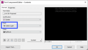
    The code in question can occur if, within your Text Component Editor, you have font overrides.

    There is a right click option that is supposed to remove any formatting. But you know what? Sometimes it doesn’t work. What to do?

    The Solution:

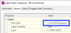
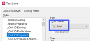
    1. Ensure you don’t actually have an alternate font selected in the Format page. It needs to match the font specified in the Text Style for the label style. FYI, if you DO have an alternate font chosen, that {\fCalibri code will not go away with this technique.

    2. Copy the “code” from the editor. Ctrl+A. Copy all of it!

    3. Paste into Notepad.

    4. Copy the same code, but from Notepad this time.

    5. Paste back into the editor.

    6. Done!

    Yes, it does work. Why? I’m not sure. There must be some hidden creatures in there somewhere. Notepad does not allow such things to linger about.

    To learn more about Civil 3D Label Styles and Fonts, or if you have any other questions, please feel free to contact us and one of our representatives will be in touch with you as soon as possible.

    Civil 3D: Recreate your Template

    Recreating a Civil 3D template from scratch is not something we look forward to, but it may be necessary at times. Read on to find out more.

    You may ask why one would need to do this. Some users will do this when they upgrade to a new Civil 3D release. I have not seen any evidence that would convince me to do this. The only time I would recreate a template is if there is a serious problem that can’t be fixed without it. The recover command does a very good job at removing anomalies that may arise between Civil 3D releases.

    So, you’ve decided to do it. What to do? There may be further steps that what you see below, but these will go a long way to making this arduous task a little more pleasant. The workflow below assumes that your original template is not completely pooched and can be successfully inserted into your new file.

    1. Open problem template:

      • Export system variables to a file.            


      • Note the assigned coordinate system in Civil 3D Settings, Files tab.   


      • Use this CTC tool to export the Civil 3D Object Layers to a file. It is found in the CIM Manager Suite.
        Civil 3D’s Import Styles and Settings tool does a poor job of restoring these. If you don’t own CTC tools, enter Civil 3D Settings and note all the object layer settings so they can be restored in the new file.


      • Export any Layer Filters. If you’re using Civil 3D, this is easy.
      • Export any Layer States.
      • Export any Property Sets (if you are using Civil 3D).

    2. Begin a new blank drawing using the acad,dwt or dwt files, and save the drawing.

    3. Import system variables from the file you saved earlier. There are many settings saved in a DWG that must be restored.
     

    4. Import the Layer Filters.

    5. Import the Layer States.

    6. Import the Property Sets and check any label styles where they are referenced to ensure they operate properly.

    7. Insert problem file and explode. Purge anomalous blocks if necessary.

    • This step will insert most of the styles and any pre-configured objects like Point Grous, Surfaces, Pipe and Pressure Networks.
    • If the original file is too far gone, skip this step. You will need to recreate any pre-configured Prospector objects.

    8. Set the coordinate system if there was one set in the original template.

    9. Import styles and settings from problem file.
    If you skipped step 4, note that this command DOES NOT import everything. See this document for more information. These may need to be dragged and dropped form the original or recreated. 

    10. In the Prospector, inspect the names of any pre-configured objects and adjust if necessary.

    11. Use this CTC tool to import object layers from the file you exported previously.

    • Restore them manually if you do not own CTC Tools.

    12. Import paper space layouts from problem file.

    13. Close the new file and run the RECOVER file to open it and check for problems.

    14. Recreate the Scale List.

    • This can be easily done by creating some text in the original file and assigning all the scales to it. Copy this text and paste it into the new file then delete the text. New scales will now be available.

    15. Test, test, test. To make sure everything works as it should.

    16. Of course, make a backup of the original file and SAVE the new file with the original name.

    Civil 3D: Plan Production Styles

    Do you use Civil 3D’s plan production tools?  Do you wonder where the styles come from, the design file, the production template?  Read on to find out.

    If you’re not familiar with Civil 3D’s plan production tools, here are the Cole’s notes.

    • Paper space layouts complete with your company’s title block and plan and/or profile viewports are created automatically along the entire length of a selected alignment.
    • A plan production template must be selected which contains a layout configured for use with this feature.
    • These layouts can be created in one of three places:
      • In the current drawing.
      • In new drawings, one layout per drawing.
      • All layouts in a single new drawing.

    When the option to create layouts in a single new drawing or multiple drawings is chosen, there are three files in play.

    • The design file
    • The selected plan production template
    • The production sheet file the tool creates

    Both the design file and the selected template can contain styles.  They could be the same styles, or they may be different.  When creating the new drawings, which of these two files does Civil 3D use as the template: the starting point?  Where do the styles and settings come from?

    The answer is both, sort of.  Here is what happens:

    1. Civil 3D uses the design file as the template.  All styles and settings come from this file.
    2. Any styles present in the production template are then duplicated into the new production sheet drawing.
    3. If there are any styles in the production template that are the same name as the design file, they are ignored.  The design file styles are maintained.

    Note that Style 3 is present in the Design and Template files.  In the Sheet file, Style 3 is the same as the Design file.

    Civil 3D: Profile Grade Intersections

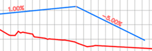
    The goal in this example is to design the profile where each grade is an even number.  It’s not as obvious as you might think.  Thanks to my colleagues Dave Hill and Jae Kwon for pointing out the proper tool.

    Read on to learn more…

    Begin by modelling the first 2 segments.  I’ll assume you know the best tools for this, but I’ll give you a hint.  Use the Grid View; it’s your friend here.


    To model the last 5% grade is not entirely obvious.  Yes, a 5% tangent can be drawn from the end of the 1% grade, but it doesn’t end in the right place.

    We sort of want to draw backwards from the end of the red profile and then extend the 1% grade.

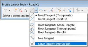
    Use this tool and follow the prompts.  First select the 1% grade, then pick Station and Elevation and the tie-in point.  Then enter the grade, in this case -5% (the grade from the intersected PVI).


    C’est voilà.


    Civil 3D: Model Existing Underground Utilities Efficiently

    Civil 3D: Model Existing Underground Utilities Efficiently

    Must you draw existing gas, tel, and other similar underground utilities for your projects?  If you’re not using the technique described below, you’re using too much time!  Read on to find out more.

    Join us at Infrastructure University, session 3, on October 20th for more information about this technique. For now:

    Facts:

    1. For nearly every civil engineering project, we must identify existing features on our construction drawings so they may not be disturbed during construction and so we may design proposed works without conflicting with these existing features. They must appear in both plan and profile.
    2. It can take considerable time to draw and label them in the plan, and even more project them into profile.
    3. When there is an edit to the alignment, the profile locations must be recalculated, taking more time.
    4. Experiments have shown that it can take 84 seconds to draw each utility. Then 26 more seconds each when the alignment is edited.
    5. Using the technique described below, the time is reduced from 84 seconds to 20 seconds. But 0 seconds when the alignment is edited.
    6. For 160 utilities:
      1. 3.7 hours using the manual technique.                   69 minutes each time the alignment is edited.
      2. 53 minutes using the automated technique.         No extra time when the alignment is edited.

    Method

    1. Create pressure network parts lists, one for each utility. Assign styles accordingly.
    2. Create pressure networks, one for each utility. Assign the parts list and label styles accordingly.
    3. Model the existing utilities as pressure networks and project them into profile. The depth below ground can be automated.

    Civil 3D: Pipes not Extending to Structures

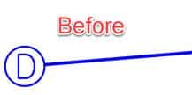
    Have you seen this before?  This is how Civil 3D’s pipes sometimes appear before and after the current annotation scale has been changed.  Not good.

    Read on to learn more…

    What is the cause?  This setting in the structure style.  You will find it in the Plan tab in the style editor.

    How to fix this?  There are several methods.

    • Never change the scale!  Easy to say, not so easy to implement.
    • Turn off that setting.  Problem is, you get this.

    • Swap each structure.  Choose the same structure.  What if there are 200 of them?  Too much time.

    • Grip-edit each structure and move them back onto their original positions.  Same problem as previous, too much time.
    • Add a wipeout to the block being used AND turn off that setting.  Our first real potential solution.  Some users report black blobs when printing to PDF when using wipeouts, however.
    • Use Project Explorer.  Select all the structures, right click, and choose the following option.  Then just click OK.  This kicks the structures in the butt and the pipes extend themselves properly.  Of course, next time the scale is changed, this must be redone but this only takes about 5 seconds.

    I prefer the wipeout option because it is permanent.  No other workarounds necessary.  If this is not an option for you, then the Project Explorer trick is likely the best option.

    Civil 3D: Alignment Creation – Free Entities

    Alignments are created in Civil 3D by selecting AutoCAD objects or by using specialized tools.  Sometimes selecting objects is appropriate, but when the alignment is required to be very flexible in terms of editability, utilizing those specialized tools can be critical.


    There are three types of Alignment segments present within those specialized tools: Fixed, Floating, and Free.  The use of these tools is not always obvious, so we have created 3 video which explains the use of them.


    The last of the three videos, Free Entities, can be viewed at this link or below.

    Civil 3D: Alignment Creation – Floating Entities

    Alignments are created in Civil 3D by selecting AutoCAD objects or by using specialized tools.  Sometimes selecting objects is appropriate, but when the alignment is required to be very flexible in terms of editability, utilizing those specialized tools can be critical.


    There are three types of Alignment segments present within those specialized tools: Fixed, Floating, and Free.  The use of these tools is not always obvious, so we have created 3 video which explains the use of them.


    The second of the three videos, Floating Entities, can be viewed at this link or below. Come back in a week or two for the next video.


    Civil 3D: Alignment Creation – Fixed Entities

    Alignments are created in Civil 3D by selecting AutoCAD objects or by using specialized tools.  Sometimes selecting objects is appropriate, but when the alignment is required to be very flexible in terms of editability, utilizing those specialized tools can be critical.


    There are three types of Alignment segments present within those specialized tools: Fixed, Floating, and Free.  The use of these tools is not always obvious, so we have created 3 video which explains the use of them.


    The first of the three videos, Fixed Entities, can be viewed at this link or below. Come back in a week or two for the next video.


    HOW OUR AEC E-LEARNING SOLUTION IMPROVES EMPLOYEE RETENTION

    This story was originally published by 

    AN AEC E-LEARNING SOLUTION CAN MAKE ALL THE DIFFERENCE FOR YOUR EMPLOYEES.

    Employee retention is one of the biggest ongoing goals for successful companies. Improving retention allows you to keep your top performers, promote from within, and avoid the time and cost of replacing staff.

    recent survey from The Harris Poll found that 70% of employees would likely leave their current organization if its training and development offerings weren’t up to par.

    Let’s explore how our AEC e-learning solution, Pinnacle Series, can help deliver the development employees are looking for and improve retention at your architecture, engineering, construction, or manufacturing organization.

    1. Promotes lifelong learning
    2. Makes workflows more efficient
    3. Personalizes training
    4. Empowers their career goals

    PROMOTES LIFELONG LEARNING

    Learning helps us grow and achieve goals throughout our lives and careers. But often, employees feel like they’re growing stagnant. If you provide the opportunity for them to learn new skills on their own terms, you’ll build the kind of culture that encourages growth.

    MAKES WORKFLOWS MORE EFFICIENT

    Pinnacle Series is full of training videos, documents, and other resources employees can use to improve their skills at dozens of important AEC programs e.g., software skills, company guidelines, health and safety knowledge, and more. And they can do it the minute they need answers, for instance, in the middle of a project. Instead of interrupting a co-worker, they can hop onto Pinnacle Series, watch a quick how-to video, and get back to work with confidence.

    PERSONALIZES TRAINING

    Employees often don’t benefit from a one-size-fits-all course enrollment or seminar that doesn’t fit their individual needs. They feel it’s a waste of their time. In addition, it can be labor-intensive for managers to figure out the required training needs for every employee, especially within larger organizations. With Pinnacle Series, the concept of personalized learning is built in. Users can take KnowledgeSmart assessments to generate a custom learning plan that fills their skills gaps without repeating information they already know.

    EMPOWERS THEIR CAREER GOALS

    By equipping your employees with new skills to move forward in their careers, you’re helping them and your organization. You can invest in and promote from within.

    Want to see for yourself how our AEC e-learning solution can help your organization? Schedule a demo or free trial of Pinnacle Series today!

    Are you a current Pinnacle Series customer? Log in now or connect with your Customer Success Manager to see how you can leverage our platform in your employee retention efforts.