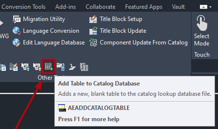
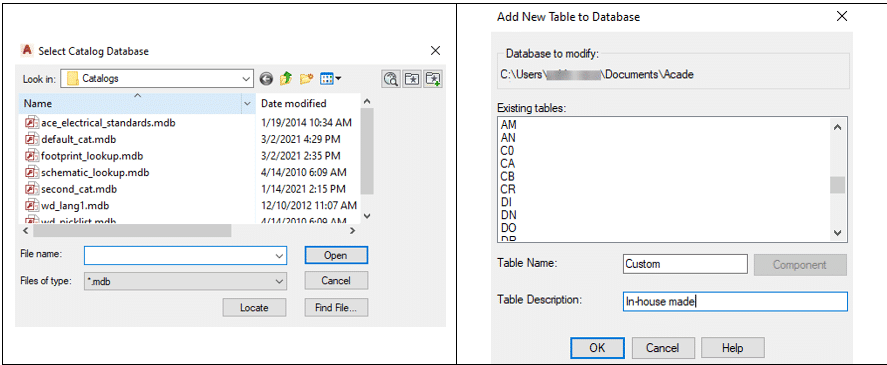
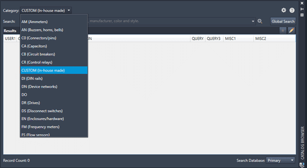
This story was originally published by Lumion on the Lumion Blog.
With Lumion, you can render more than a building. Render your client’s dream home, render a story about design that moves emotions, render the space where life happens.
A building begins as a structure. Walls. Floors. Roofs. Windows and doors. All expertly crafted into a beautiful arrangement of form and function.
When looking at the 3D model, however, you might feel as if something is missing. Maybe it doesn’t capture the energy and atmosphere of the space and its surroundings. Perhaps it doesn’t ignite emotions or make you want to be there. Whatever it is, there’s something about life that’s just not easy to show in CAD.
With Lumion, you can bring your vision to life and tell a richer, more immersive story about the design’s role in the real world. A story that sparks imagination and helps clients fully visualize how life could unfold within those four walls.
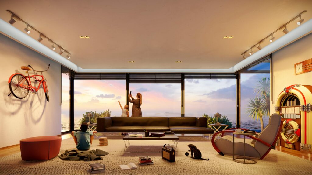
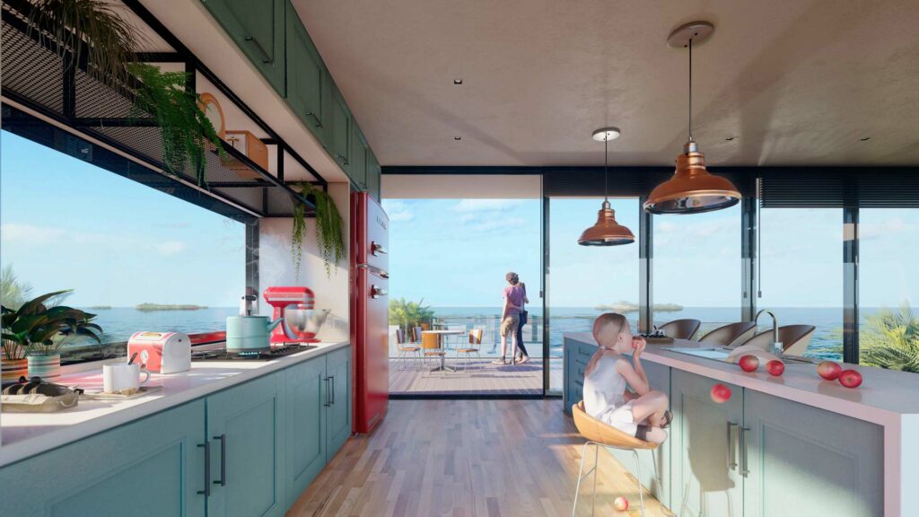
From the small experiences you share with others to the objects that decorate your home, life is full of feeling. The sofa, coffee table and chairs in the living room, for instance, become a gravitational center where families share peaceful moments together. Papers and pens and books are scattered across a busy home office desk, alongside used coffee cups and photos of loved ones. In the kitchen, the teapot boils and toast pops out of the toaster, signaling the start of a new day.
These are not just objects, they are reflections of life. They fill spaces with character.
Lumion helps architects unveil their designs as lived-in spaces, capturing the deeply personal connection between a building, the people who inhabit it, and all the unique objects they bring with them.
You can render more than a building. Render your client’s dream home, render a story about design that moves emotions, render the space where life happens.
What’s new in Lumion 11.5
The latest version of Lumion reinforces its ability to make spaces feel alive with the everyday activities that occur there. You can let your imagination loose and tell a story about a room, a building, or even the entire project, exactly as you see it in your mind’s eye.

Lumion 11.5 Pro comes with 123 new objects* in the content library, making it easier to add a human, personal touch to your renders. You can find 73 new retro-inspired objects that reveal the unique identity of spaces, including:
| 36 eye-catching kitchen objects, including blenders, refrigerators, toasters, mixers and more. | 12 furnishings from another era, including café tables and chairs, a jukebox, a popcorn maker and more. |
| 11 timeless pieces of office furniture, including sofas, desks, chairs, table lamps and more. | 14 other stylish items, including clocks, radios, a sewing machine, TVs and more. |
Additionally, you can express delight throughout your scene with 50 new 3D characters, including a diverse variety of children, teens and adults of different backgrounds and cultures.
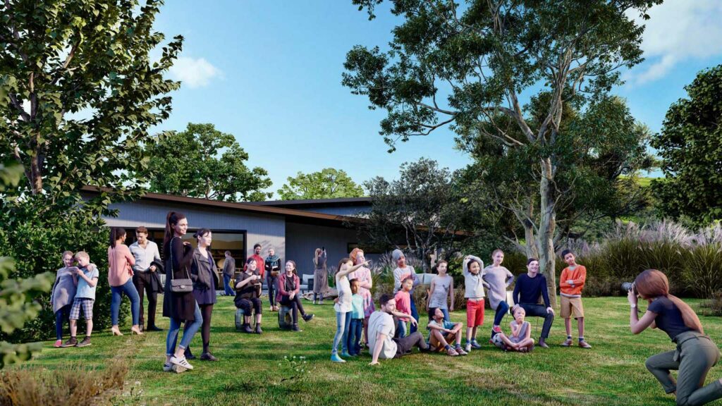
These cheerful non-animated characters are ideal for communicating context, scale and emotion in the background of your project, whether it’s a sunbather relaxing on the grass, a child looking up with wonder, or a couple enjoying a beautiful view together.
There are infinite stories to tell about your design with the mix of new 3D characters and retro-inspired objects in Lumion 11.5. When combined with Lumion’s existing content library of over 6,300 assets* and over 1,250 materials*, you’ll find yourself on a smoothly paved road to rendering creativity, to bring your designs to life.
Availability
Lumion 11.5 is available from June 1st, 2021, as a free update for Lumion 11 and Lumion 11.3 users. Lumion 11 users can download the updated version on your Lumion Account.
Have more questions?
Contact us today info@solidcad.ca