Dynamo Studio is typically associated with Revit; however, it offers a fantastic platform for algorithmic-driven design and easy parameter manipulation in Fusion 360. It also features great T-spline and surface support for complex geometry creation, for those wishing to bring a degree of parametric control to their surfacing with ease.
The add-in supports a bi-directional data exchange between Fusion 360 and Dynamo Studio, allowing users to create visual logic for Fusion 360 parameters update. It can be downloaded here: https://apps.autodesk.com/FUSION/en/Detail/Index?id=74731490955641349&appLang=en&os=Win64
It provides an ability to use a visual editor environment to modify Fusion 360 model parameters, view and use them in complex logical graphs. Fusion 360 parameters will be automatically updated from Dynamo Studio using custom input and output nodes.
Dynamo for Fusion 360 Supports Dynamo Studio 2017 version: 1.1 – 1.3.
The benefits of using Dynamo with Fusion 360 are:
- Very complex and rapidly reconfigurable T-Spline surfacing is
- Parameter driven components can be modified live using sliders to adjust
- Parameter driven components can have logic integrated to link different parameters and make automatic adjustments according to conditional
- Parameter driven assemblies can be modified live and can adapt if setup
- Parameter driven assemblies can have logic integrated to link parameters from different components to respond to changing geometry according to conditional
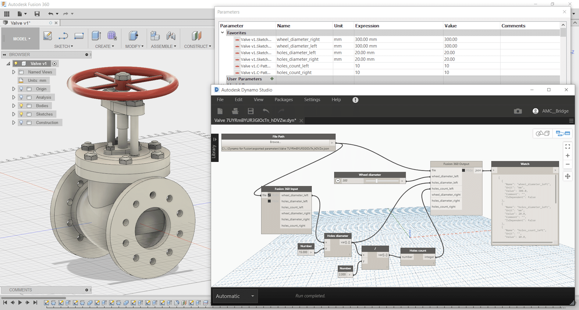
One of Dynamo – Fusion 360 Workflows is called “Synchronous workflow”. It is directly manipulating parameters listed in the parameter table in Fusion 360. This can enable rapid reconfiguration of assemblies and components by using sliders, or logic can be incorporated to describe relationships between geometry. If you have not tried, here are some simple steps to try:
Step 1: Create a simple Fusion part with some name parameters as shown:

Step 2: Save and name the part as “Dynamo-Fusion”
Step 3: Go to Tools -> DYNAMO FOR FUSION to run Dynamo

Dynamo will create a same name parameter file with extension “.json” that contains all extracted parameters from Fusion 360 part and stored under: C:\Users\ (your username) \AppData\Roaming\Autodesk\Autodesk Fusion 360\API\AddIns\Dynamo for Fusion\exported parameters\

Step 4: In Dynamo’s search bar, search for “output” and insert “Fusion 360 Output” node. Repeat search for “Slider” and insert “Number Slider” node.


Step 5: In Dynamo, connect File Path to “Fusion 360 Output” and “Number Slider” to any parameter and set Min, Max and Step. Use the slider to size or adjust the features.

If you would like to manipulate other parameters, then just add more sliders. Simply select the slider node and use Ctrl+C to copy and Ctrl+V to paste it. After that you can customise each slider values (Max, Min, Step) and connect it to any of the parameters and watch the part update. You can even connect a slider to more than one parameter (i.e. to make a square cut).
Using Dynamo with Fusion360 can be fun and simple. Try it and have fun with Dynamo for Fusion 360.