• Canadian Flag Proudly Canadian Owned and Operated
  • Sharing is Caring

    In todays manufacturing world there is a bigger demand on sharing data with all stakeholders outside your company.  This could be your supplier, buyer, manufacturing team and they could require viewing the drawing to the 3D model that you create.  Using Autodesk Vault you can created a shared view for your outside stakeholders and value chain.  Autodesk provides this as a free viewer, markup and comments, all they would need to do is sign up for a free Autodesk account.  Also Share View is a great tool to use internally as well to do digital markups and collaboration outside the engineering department.

    To use Share View simply log into Autodesk Vault and find the model or drawing you would like to share and right click and select Share View:

    You may be prompted to login using your Autodesk account, once you have logged in the Create a Shared View dialog box will prompt you to enter a name:

    Enter the name you would like and then click on Share, and it will start to process the shared view.

    Once complete a Share View Complete Dialog will display that it was uploaded successfully and it will give you a copy link and view in browser option.

    Copy Link – This is the link you can email to your stakeholders for them to open and view online.

    View in Browser – this will open the shared view in your browser for you to view.

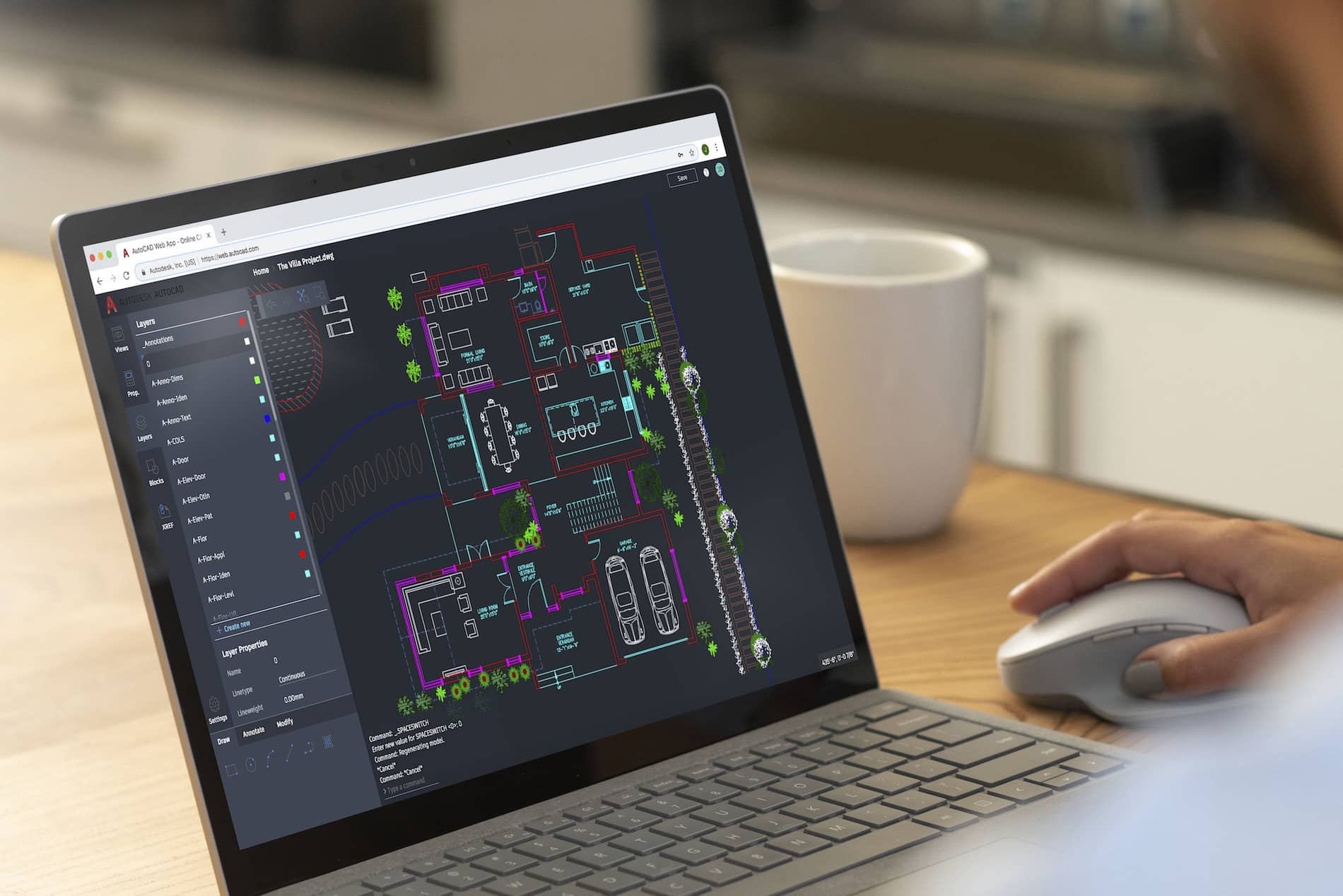
    Clicking on View in Brower it will launch the Share View online:

    This view will only be available for 30 days on Autodesk Viewer.  Only users who are invited though the link or when selecting share will have access to the model or drawing.

    Once singed in users can markup, add comments and when clicking on share, it will send the users in Vault a notification that someone has made a comment on the drawing.

    To make a comment simply select comments to type a comment directly.  Anytime you click on Markup the markup changes will be saved on the comments tab when you select Post.


    In Vault client to view the comments or markups make sure that Shared Views Panel is turned on.  If not turned on simply go to View > Shared Views and make sure there is a check mark beside Shared Views:

    In the Shared Views panel the comments and markups will be shown:

    To make a comment back simply click on Reply and it will take you back to the Autodesk Viewer to continue the collaboration between your company and stakeholders.

    As you can see getting data to correct users at a timey manor is critical in todays business.  Autodesk Vault Professional and Shared Views enables you to connect the value chain and make sure everyone has the data they need.  Also, Autodesk viewer is not just limited to Inventor or AutoCAD drawings and models if you go directly to viewer.autodesk.com you can sign into your account and upload the following files for collaboration:


    Remember Sharing is Caring and happy collaborating!!

    AutoCAD and Bluebeam

    Many users create PDF files from AutoCAD products as PDF seems to be the standard digital format.  There are three issues you may run into and some settings to consider if you use Bluebeam Revu as well as AutoCAD.
    Viewports


    First, you may see this message when opening PDF files using Bluebeam Revu (not the free viewer) which were created from AutoCAD using Autodesk’s DWG to PDF print driver.  These “viewports” are artifacts contained within the PDF file to which Bluebeam Revu alerts you when you open a file containing them.  ALWAYS say yes to removing these artifacts.  If you don’t, they will very likely affect the accuracy of any measurements you make in Revu.  If you skip past this message without selecting Yes, the viewports can be removed from the PDF in Revu’s measurement panel.


    Why do they exist in the first place?  It seems to be an issue with Autodesk’s DWG to PDF.pc3 file.  PDF’s created using Bluebeam’s PDF printer do not contain these anomalies.  Here is an Autodesk  discussion group thread discussing these viewports.  Interestingly, it indicates that these viewports can cause an issue when measuring using Adobe Pro, but there appears not to be a solution there, where Revu does indeed catch the existence of them.

    Searchable Text and SHX Fonts

    The second issue is searchable text.  Many AutoCAD users still use Autodesk SHX fonts.  There are several reasons to avoid using SHX fonts; not the least of which is that when a PDF is created containing them, that text will not be searchable when opened in any PDF reader software.  If you want your recipient to be able to search text, and you very likely should, do not use SHX fonts in AutoCAD.  Use a True Type font, such as Arial instead.  This is with one exception.  With Bluebeam Revu, SHX text is in fact searchable, but you must enable “Search Markups”.  More detail about this I the section below “Odd Markups”.

    If you’re a Bluebeam Revu user with the CAD version or better, and you prefer to use its PDF print driver instead of Autodesk’s, there is an option to enable SHX fonts as outlined in this article.  Better, do use a True Type font as mentioned above, but there is one more setting you must enable.  A PC3 file must be created using the Bluebeam print driver and then this option set in the printer properties in AutoCAD.  It defaults to TrueType as graphics and your text will not be searchable if it’s not changed.

    Odd Markups in Revu


    Lastly, using Bluebeam Revu (not the free viewer) to open a PDF created by AutoCAD using its DWG to PDF printer, you may see “markups” already contained in the PDF.  There will be one markup for each text object in the file, indicated by the AutoCAD SHX Text author.  That adds up to a lot of markups if it’s a file with many text objects.  This can affect the performance of the file within Revu and they will definitely be in the way when creating normal markups.  These markups are only required if you need to search SHX text; they cannot be deleted with Revu tools.  They can be Flattened in Revu prior to adding your own usual markups, or they can simply be filtered out if you don’t wish to see them.  Don’t worry, the text in the PDF will not disappear.  I do not have access to Adobe Pro to see if this is an issue there as well.

    These “markups” are created when printing from AutoCAD using the DWG to PDF driver and it is an Autodesk feature.  In AutoCAD, there is a variable named PDFSHX.  Turned on, a value of 1, enables these “markups” in the PDF file which results in searchable text.  Turning it off will result in no “markups” and non-searchable SHX text.  Here is an Autodesk document outlining this feature.  SHX text may or may not be searchable depending on the PDF reader in use.  For example, the Bluebeam Revu free viewer cannot search SHX text, but the paid version can.

    This issue does not occur with PDFs created in AutoCAD using Bluebeam’s printer driver.

    Working Remote Sessions With Gautam Shenoy and Bluebeam

    This story was originally published by Bluebeam, Inc. on the Bluebeam Blog.

    In light of many states’ stay at home orders in light of the nationwide COVID-19 pandemic, many professionals in the construction, architecture and engineering world have suddenly transitioned to working from home for the foreseeable future.

    Construction is still considered an “essential” business in many states, meaning many field workers are still heading to jobsites each morning. However, industry workers who spend most of their time collaborating with coworkers in an office are now dealing with the new reality of remote collaboration on projects, presenting some new challenges—and advantages.

    In an effort to share and highlight how industry professionals are making this transition, the Bluebeam Blog will be publishing a series of video interviews with individuals to see how their work-from-home transitions have gone so far.

    In this first installment, we talked with Gautam Shenoy of Steinberg Hart. Here are the highlights from our conversation, along with time stamps of those parts of the video in case you want to skip ahead.

    [00:30] Is the construction industry still working as “normal”?
    “The industry is definitely humming along. … We haven’t seen a slowdown on projects that are in construction; we have seen a little bit of a change in the pace of projects that are ongoing but on the drawing board, so to speak.”

    [01:15] What has changed most since working from home started?
    “I think what’s changed the most is the way we communicate. We were so used to being in an office and emailing each other. I feel like it has really changed. I feel like working remotely has sparked video conferencing and teleconferencing and taken it to a new level. People are now wanting to constantly keep in touch with people even though there’s no physical presence.”

    [02:07] How has working from home changed some job tasks?
    “One of the things that I wanted to point out is that Bluebeam has always been ahead of the curve, and I say that as even before the idea of cloud-based collaboration was so mainstream as it is today. Regardless of where you are, with Bluebeam Studio you are able to keep working on a project. On a day-to-day standpoint, not only are we using Bluebeam as we always have, but we’re also using other platforms like Microsoft Teams to plan and track our goals.”

    [04:21] “Designers have a completely different way of communicating. You have to understand that in the design realm, the way people communicate in the design phase is so different than when people are marking up drawings and tracking benchmarks. So, Bluebeam has become sort of a preferred methodology of communicating even in the design phase.”

    Working Remote Sessions

    Dynamo for Autodesk Fusion 360 – Made Simple

    Dynamo Studio is typically associated with Revit; however, it offers a fantastic platform for algorithmic-driven design and easy parameter manipulation in Fusion 360. It also features great T-spline and surface support for complex geometry creation, for those wishing to bring a degree of parametric control to their surfacing with ease.

    The add-in supports a bi-directional data exchange between Fusion 360 and Dynamo Studio, allowing users to create visual logic for Fusion 360 parameters update. It can be downloaded here: https://apps.autodesk.com/FUSION/en/Detail/Index?id=74731490955641349&appLang=en&os=Win64

    It provides an ability to use a visual editor environment to modify Fusion 360 model parameters, view and use them in complex logical graphs. Fusion 360 parameters will be automatically updated from Dynamo Studio using custom input and output nodes.
    Dynamo for Fusion 360 Supports Dynamo Studio 2017 version: 1.1 – 1.3.

    The benefits of using Dynamo with Fusion 360 are:

    • Very complex and rapidly reconfigurable T-Spline surfacing is
    • Parameter driven components can be modified live using sliders to adjust
    • Parameter driven components can have logic integrated to link different parameters and make automatic adjustments according to conditional
    • Parameter driven assemblies can be modified live and can adapt if setup
    • Parameter driven assemblies can have logic integrated to link parameters from different components to respond to changing geometry according to conditional

    One of Dynamo – Fusion 360 Workflows is called “Synchronous workflow”. It is directly manipulating parameters listed in the parameter table in Fusion 360. This can enable rapid reconfiguration of assemblies and components by using sliders, or logic can be incorporated to describe relationships between geometry. If you have not tried, here are some simple steps to try:

     Step 1: Create a simple Fusion part with some name parameters as shown:

    Step 2: Save and name the part as “Dynamo-Fusion”

    Step 3: Go to Tools -> DYNAMO FOR FUSION to run Dynamo


    Dynamo will create a same name parameter file with extension “.json” that contains all extracted parameters from Fusion 360 part and stored under:  C:\Users\ (your username) \AppData\Roaming\Autodesk\Autodesk Fusion 360\API\AddIns\Dynamo for Fusion\exported parameters\

    Step 4: In Dynamo’s search bar, search for “output” and insert “Fusion 360 Output” node. Repeat search for “Slider” and insert “Number Slider” node.


    Step 5:
    In Dynamo, connect File Path to “Fusion 360 Output” and “Number Slider” to any parameter and set Min, Max and Step. Use the slider to size or adjust the features.


    If you would like to manipulate other parameters, then just add more sliders. Simply select the slider node and use Ctrl+C to copy and Ctrl+V to paste it. After that you can customise each slider values (Max, Min, Step) and connect it to any of the parameters and watch the part update. You can even connect a slider to more than one parameter (i.e. to make a square cut).

    Using Dynamo with Fusion360 can be fun and simple. Try it and have fun with Dynamo for Fusion 360.

    Civil 3D 2021 is Here

    It’s that time of year again folks; Autodesk has released their flagship Civil Engineering product in Civil 3D  2021.  Here is an Autodesk article explaining the new changes.  Here are my favorites from this release.

    Format

    There is no format change this year.  Excellent!  You may share your Civil 3D files with users back to 2018.

    Pressure Networks

    There has been significant development to this feature.  If you have not been using pressure networks due to feature limitations, it is time to rethink your approach; these tools are good!  We now have path-based pressure network Pipe Runs in both plan and profile.  The image below shows a grip-edit to a pressure main.  The bend was automatically swapped after the grip-edit.

    Do you need your pressure network to maintain a 1.5m cover below your corridor surface?  Here, the pipes are dynamically linked to the design profile at a 1.5m depth.

    Infraworks Interoperability

    More collaboration features have been introduced, such as:

    • Civil 3D corridors can now be mapped to Infraworks Component Roads and remain dynamic to the drawing when reimported.
    • Infraworks bridges are now supported within Civil 3D, stylized labeled in profile views.  There is a new Bridges node in the Prospector.

    Scripting

    There are additional nodes and functionality related to Dynamo scripting.

    Working From Home with HIVE – CTC

    This article was created by CTC Software

    So, you need to work remote from the office and you have discovered it is a bit of a pain for production. Or, perhaps you have yet to discover the pains of extended remote work and you want to be prepared? CTC Software has tools to make all aspects of production more efficient, including the remote workforce.

    The biggest delay when working remotely in Revit, after the project model access, is getting and loading content. The project model has been properly solved by Autodesk’s BIM360 eco system. Sadly, that system is not very efficient at holding the content and allowing it to be loaded into project models. This content loading process typically involves someone using a VPN connection to remotely access the office network, then browsing across that VPN connection. When the time comes to load family content it is rather slow, but even worse is when system families or typical detail views must be accessed. These pieces of content are stored in project models, and these models can be rather large. Opening and transferring settings from these models is extremely slow across VPN.

    CTC has heard it said, “Well, I’ll just use Google docs, or Dropbox then…” Well, this may work, but keep in mind, small company libraries are about 1GB of content per Revit version so this could easily mean storing and syncing 4GB of Revit content, and this is estimating conservatively. Most firms have way more than that.

    So, what is the solution? CTC Has a toolset called HIVE. It is tuned to manage Revit’s custom libraries but can also be used for any kind of content. Since we are discussing Revit here, understand this, HIVE allows easy google-like searching of the regular loadable families, System families, typical drafting views, Schedules, and even fully assembled sheets. This all can be done with very minimal setup, and users get the content they need on-demand. All they need is an internet connection. This would not require any VPN for the content stored in HIVE.

    CTC has run demonstrations of HIVE from conferences like Autodesk University and BiLT. These conferences often have acceptable but certainly not speedy internet, and sometimes the internet at these events can be very unstable. While there, CTC often conducts HIVE demonstrations, browsing for any needed content with no perceptible delay.

    What does this mean for you? Well, your BIM Management team can easily configure HIVE to host all needed Revit Content, and your workforce can access it from any workstation connected to the internet. They will need the internet anyway to work on BIM360, so the system requirements and connections are already in place for them to use HIVE almost instantly.

    Contact your local CTC representative to get your trial of HIVE and understand how you can purchase this perfectly tailored solution for times just like the ones we currently find ourselves in.

    Contact:

    Mughees Altaf
    Account Manager — AEC Productivity Tools
    mughees.altaf@solidcad.ca 

    AutoCAD 2021 is Here

    It’s that time of year again folks; Autodesk has released their flagship product in AutoCAD 2021.  Here is an excellent article explaining the new changes.  Below are the features that are close to this BLOG writer’s heart.

    Format

    There is no format change this year.  Excellent!

    Enhanced Commands

    Trim and Extend have new default behavior resulting in fewer clicks.
    Revision clouds are now their own object.  Including a new Arc Length property.

    The Break At Point command can now be repeated resulting in fewer clicks.
    Drawing version history comparison for files stored in cloud services such as OneDrive and DropBox.

    The block palette now contains a Library for blocks stored in cloud services or other folders.

    AutoLISP

    A brand new AutoLISP development interface which uses Visual Studio Code with a LISP extension.  Auto-complete functions and parentheses.


    Manage drawings more efficiently with Batch Link | Revu 2019

    This article was originally published by Bluebeam, Inc. in the Knowledge Base.

    The Batch Link® feature automatically creates hyperlinks for a group of PDFs, like when you’re working with a multi-drawings set or details on drawing sheets. You can specify the criteria used to create these hyperlinks or automate the process using filenames, page labels or the AutoMark function.

    You can also use Batch Link to:

    • Create a navigational link on your title block that takes you to the sheet index.
    • Add Studio Project files to the Batch Link wizard.

    Learn how to take your batch linking to the next level with these tips!

    If the set of files you’re going to batch link contains a title block, you can use it to create a navigational link that takes you back to the sheet index, similar to a home button. All you have to do is swap out the search term generated in the Batch Link wizard (usually the sheet number) for your project number. If you don’t have a project number, you may use any text string found on the title block of every page.

    1. Go to Batch > Link  > New. The Batch Link wizard opens.
    2. Add the PDFs to be processed.
    3. Select Next. The second page of the Batch Link wizard opens.
    4. To generate your list of search terms, choose the Page Region option, then click Select.

    Next, define a region on the PDF and generate Search Terms

    1. Click and drag to define a region on the PDF. When the region has been defined, the AutoMark dialog box appears. Click OK when finished.
    2. When the correct sheet number displays next to Search Term in the Scan Preview section, click Generate. The Manage Links list is automatically populated.

    Lastly, look through the Search Terms and edit destination

    1. Look though the generated list of search terms to ensure they match their correct destination.
    2. Change the search term for your project number (or any text string from the title block).
    3. Select OK, then Run.


    Now you have a link on your title block that takes you back to the sheet index.

    Have you ever wanted to Batch Link your Studio Project? You can do this by adjusting your Studio Preferences.
    To enable Studio Project files for Batch Link:

    1. Go to Revu > Preferences  (Ctrl+K).
    2. From the sidebar, select Studio and then Options.
    3. Clear the Open and save files to Studio from toolbar only check box.
    4. Open the Project file.
    5. Go to Batch > Link  New.
    6. Select Add Files and add your Project files.

    Now you can add your Project files to the Batch Link wizard.

    Roof Truss versus Rafter and Extending to Core tool

    I would like to point it out two tools that can make a big difference when designing roofs, the Truss or Rafter tool and the Extending to Core tool. They also affect the shape and size of the eave truss.

    Revit offers to options to justify the roof and the reasons why is because the bearing condition is very different between the two. The Rafter or Truss option is only available if we choose the Pick Walls tool.

    When we select Roof by Footprint, and the Pick Walls tool, we see at the Options Bar the Extend to wall core check box.

    The diagram below explains the different roof configurations that result from switching on and off the Overhang Extend to Core option and the Rafter or Truss option. When the Extend to Wall Core is activated, Revit will measure the overhang from the core. When it is not activated, it will measure the overhang from the exterior face of the wall. Also noticed how the Truss and the Rafter connections change. The Truss sits on the Exterior face of the wall while Rafter sits on the interior face of the wall.

    Another advantage of using the Pick Walls tool is to assure stability when editing the overhang. When we use the Pick Lines tool, Revit create a line that not attached to the wall. Notice that there is no option to change between Truss or Rafter. Below I draw a roof using the Pick Lines tool and another one using the Pick Wall command. See the difference when I change the overhang dimension.

    Notice that when using the Pick Lines tool, the roof and the wall are not aligned and to fix that we would have to drag the roof manually. On the contrary, using the Pick Walls command, the roof remains aligned to the wall. Whenever is possible, it is best to justify the roof using the Pick Walls tool when creating the roof footprint. By doing that we are avoiding future issues, saving time and getting the most out of Revit!

    Path of Travel update on Revit 2020.2

    Since my last post about the path of travel, Autodesk made a very useful update on the path of travel tool.

    The path of travel was calculated automatically by Revit picking the start and end point. Now we have the ability to add waypoints along the path of travel. This allows us to drag the points and adjust the path. You can also delete the waypoints to restore to default position.

    To activate the tool, simply select the path of travel. The tool will appear under the Modify| Path of Travel Lines. Select the Add Waypoint, click on the path of travel and drag it to adjust it. To delete it, select the Delete Waypoint and click on the point.