With the release of the 23.0.0 version of all the CTC Software tools, CTC has taken the opportunity to update their licensing model.
Licensing for any of the CTC suites of tools was broken up into tiers of licensing with maintenance attached or differences depending on how many employees were in the company. It was tedious to explain, and not too efficient to implement.
Starting with the 23.0.0 release of the suites, CTC is moving to a CSL model of licensing. This Cloud Shared Licensing is much more in line with the SaS model of software delivery. However, this is deliberately not the named user licensing that Autodesk has moved to. The CSL model is intended to simplify access to the tools while maintaining the flexibility of the network licensing style of license.
Put simply, the CSL model is a cloud hosted version of the network licensing most of us are familiar with. Which means there is no need for installing license managers on local servers, all users need is internet access to use the CTC tools. The CSL is hosted on the new CTC website that was launched in conjunction with the 23.0.0 suite releases.
With the new website, there have been additional efficiencies added by automating tasks like the option to renew automatically and automatic fulfillment of orders. The new website will also give administrators detailed insight into their teams’ suite usage and the ability to control the allocation of licenses with the creation of Groups of users on the website.
The move to CSL was done for efficiency for everyone. This simplifies and standardizes access to the tools, allows for instant license allocation, offers reporting on usage of suites and tools, and simplifies pricing models.
One thing to note is that the 2022 and older versions of the CTC Suites still only work with the legacy licensing and cannot use the CSL model.
If you have any questions regarding this new licensing model for the CTC Software, your SolidCAD Account Manager will be more than happy to help.
CTC Software has enhanced their licensing model in June 2022, all new licensing is facilitated through Cloud Shared Licensing (CSL) now. This shift to CSL means that moving forward the 2023+ releases of their tool sets will only be available through CSL. It marks a big jump in flexibility and tracking of license sharing and puts CTC ahead of the curve in the industry for license facilitation. All you need is an internet connection and access to their website to use your CTC tools now.
What is Cloud Shared Licensing and how is it different from the Network Licensing or Named User Licensing?
CSL is NOT at all the same as the Named User licensing that most software has migrated to. We can think of CSL as network licensing managed from the cloud. This is preferable to the network licensing because the license manager doesn’t need to be installed on your server and setup time is greatly reduced.
Named User Licensing ties the license of the product (A seat of Civil 3D for example) to a user’s email, this is intended to restrict the use of that product to that single user among other thing. CSL is still a pool of licenses that you would use a login to access. So 100 employees could have logins to access a pool of 10 licenses, but each license can only be used by 1 person at a time.
What does this change mean for my company and me using the tools?
As mentioned above, this will allow you to have access to your CTC tools with a CTC Account login and access to internet. No need to even be connected to your company network to pull a license from your pool of CSL license.
Importantly, CSL will still allow compatibility with the latest 5 versions of your Autodesk software.
On the IT and license management side of thing, CSL is incredibly easy to setup, manage, and report on license usage. Through the CTC website we can access the license portal to set up and assign licenses to user groups, borrow licenses to access offline, revoke licenses, setup auto-renewals, and manage roles & admin rights associated with your CTC products.
How do I manage my licensing now?
Accessing the licensing portal is done through the https://ctcsoftware.com website and clicking on the person icon next to the shopping cart.
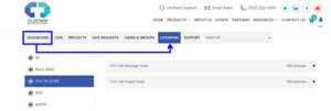
After logging in, you will be directed to the portal dashboard where you can navigate to licensing to see all your CTC products.
From here you can invite user, add them to user groups, assign roles, and assign access to your various products.
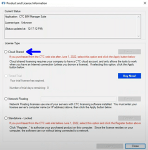
From within the Autodesk software once the tools are installed on the work station, the user ill just have to click on one of the darker colored tools to bring up the “Product and Licensing Information” dialog box.
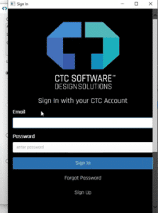
Once you click the Cloud Shared and click Apply, it will bring you to the Sign In window to enter your CTC Account credentials. You will only be required to sign in the first time you access the tools and will give you access to all the tools that you are assigned to in the licensing portal.
The new Cloud Shared Licensing is the future for CTC Software and I hope this article has shown you some of its benefits. CTC has done a great job with a couple webinars linked below to explain the picks and clicks in more detail for setup and management of the license portal, so I would encourage you to watch them as well.
Note for their Network and Standalone end of life:
May 1st, 2023: You will no longer be able to buy Network or Standalone Licenses. Only new seats of CSL.
May 1st, 2024: You will no longer be able to renew existing Network or Standalone Licenses. This marks the point where CTC tolls will only be available as CSL.
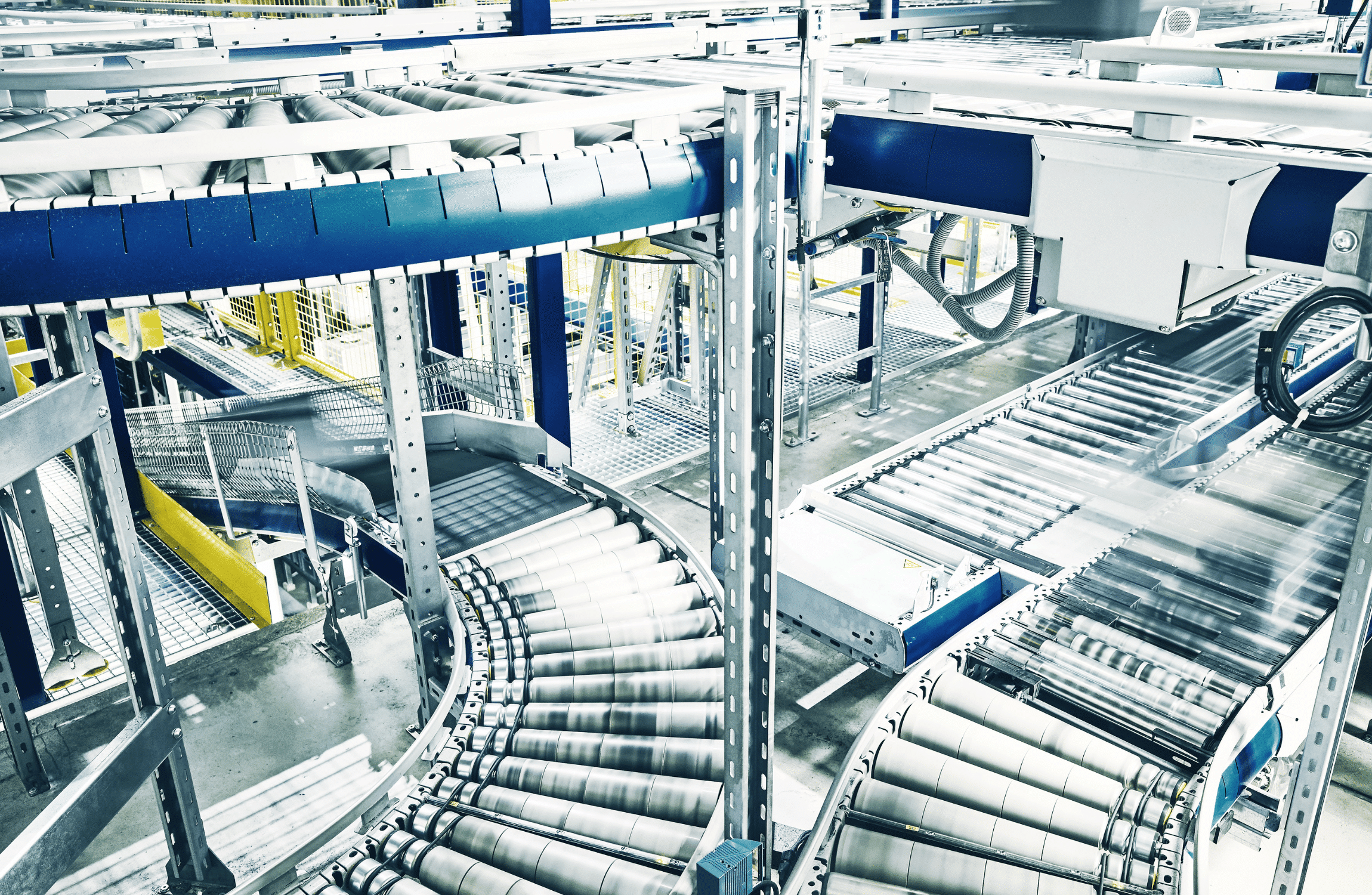
Founded in 1988, mk North America is a member of, and North American headquarters for the mk Technology Group. They design, engineer, and manufacture a wide variety of conveyors including belt conveyors, roller conveyors, timing belt conveyors, chain conveyors and flexible flat top chain conveyors; as well as workpiece pallet-handling conveyor systems, and extruded aluminum framing (including guarding and linear motion systems). They offer incredible variety and flexibility, and their products have proven themselves worldwide in a broad variety of applications and industries.
A Smooth and Easy Transition to Variant!
The Challenge
Like many other manufacturers, mk North America uses Autodesk Inventor and iLogic for their product designs. They previously used Autodesk Configurator 360 to make the designs available on their website for customers to create their own configurations but needed to find a new option once Configurator 360 was no longer available. They did diligent research into what products were available and explored all their options. For a while, they considered building their own configurator but realized it would require a complete overhaul of their current systems and workflows, costing them more time than they could spare.
Once it was clear to mk North America that they would greatly benefit from some outside expertise, they turned back to online research and found SolidCAD’s newly announced cloud-based configurator, Variant.
The Solution
Variant was just what they were looking for. Since our online configurator uses Autodesk Forge Design Automation API for Inventor, it can directly leverage iLogic code in existing CAD models. This allowed mk North America to smoothly transition to Variant without wasting valuable time on re-work or any major disruptions to their established workflows.
Design engineer, Will Peters, spoke about how they were not new to configurators. Since they were already using Configurator 360, almost every other solution they investigated would require massive changes on their end. “The nice thing about Variant,” he explained, “was that we only needed to make some pretty minor adjustments. It operated on the same platform so it wasn’t as full of a process as it would have been with another product.”
mk North America expressed how impressed they were with the SolidCAD technical team’s expertise and communication. Although they were already very familiar with Autodesk Inventor, they were able to learn more in depth information about what goes on in the backend and how all their systems work together. Ultimately, it was a great benefit to continue working with the platforms they knew, and they are grateful they did not decide to face this challenge on their own.
An extra benefit to mk North America was our team’s ability to thoroughly assess and understand their needs. “We had looked into a couple different solutions,” explained Kate Nadeau, marketing manager at mk North America, “the big thing that pushed us this direction was that [SolidCAD] was still developing the tool when we signed on. We knew that we would have a voice… Even though the major framework was there, knowing that we would get our needs met was huge.”
Take a look at mk North America’s instance of Variant called CAD360 on their website to configure your own conveyor today!
Testimonial
Variant was an obvious choice for us as we looked for a solution to our online product configurator.
The tool is very easy to learn and is customizable to your exact needs – which gave us the flexibility to offer a wide range of products in a single online catalog. The user interface is very intuitive and allows us to maintain, update, and improve our product offering in real-time. Along with Variant’s powerful services, the team at SolidCAD has been an absolute pleasure to work with. They are very accommodating and are eager to teach tips & tricks, explain functionality, and work through problems until they’re perfected. Choosing Variant for our online configurator was an easy decision, and it has exceeded our expectations.
Vent-A-Hood was founded in 1933, creating residential ventilation for cooking. Vent-A-Hood was the first manufacturer of home cooking ventilation and range hoods and the creators of a proprietary system called the “Magic Lung”, which uniquely…
If you’re an Autodesk Docs/BIM 360/ACC user, this update is for you. A major update is now available. Previous versions were numbered 15.x.x. We are now on 16.x.x.
Here is a feature matrix that compares 15.x to the new 16.x.
Read on to find out what’s new.
It is not recommended to have some users on 16.x and some on 15.x. It is not a requirement to upgrade all users to 16.x, but it is recommended due to workspace and permissions changes.
New Behavior:
Let’s start out by outlining some new behavior that will stump you if you didn’t know. In previous versions, when a design file is dragged into a Docs folder, all reference files would be uploaded automatically. Now, only the design file is uploaded, no references. There are options, however which I will outline next.
Upload Files and References tool:
This is the tool you should be using to upload files. That same design file can be dragged into this new interface and its references will be listed and uploaded. It’s your chance to visualize all file relationships prior to uploading.
Performance:
File saving, opening, locking, and other file access tools are now faster.
Home Screen Changes:
Current processes can be easily viewed after clicking the DC tray in Windows.
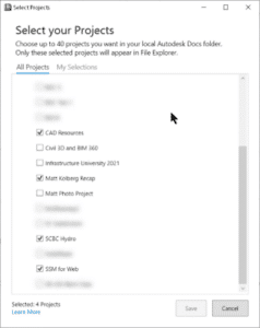
Select Projects:
You no longer need to have all your projects displayed and sync’d. Let’s say you’re invited to 30 projects. Previously, all 30 would be shown in Windows File Explorer. Now, only selected projects are shown. Up to 40 projects can be sync’d.
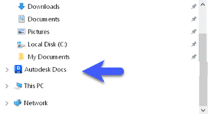
File Explorer:
Autodesk Docs is now in line with “My PC”. Also, the default workspace has been changed to C:\users\USERPROFILE\DC.
File Explorer:
Most of the usual right click options now exist for folders and files. Delete, create shortcut, etc. One new one could be a game changer. Always keep on this device. Folders and files can be selected to automatically synchronize to your local drive without having to open the file or click Sync. When Free Up Space is used, folders tagged with Always keep… are retained.
This is significant for al least one good reason: CAD Resource files. CTB, Blocks, Civil 3D Pipe Catalogs, etc. can now be stored in an ACC folder and forced to be sync’d at all times locally.
File Locking:
Most non-Autodesk files get locked when opened. MS Word DOCX files, for example. Notepad documents and PDFs opened from within a browser window are not locked. PDFs opened from Bluebeam or Adobe are locked.
Free Up Space:
Using a Windows setting, space can be freed automatically. See this document.
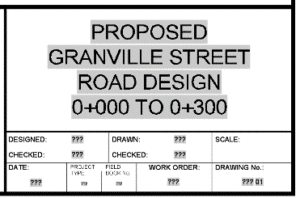
Your sheet titles are too long for a single line in your title block and,
You use the sheet set manager to control these titles and,
You would like to control where the line break occurs…
Read on…
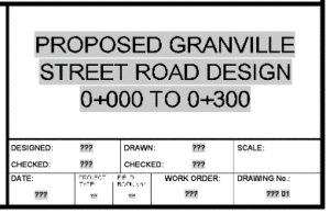
Multi-line attributes are handy when the information needs to wrap to additional lines. This attribute can contain a sheet set field which displays the title of the sheet. The attribute width can be adjusted to any width and the text will wrap automatically.
But what if we don’t like how the text is wrapped? Maybe we want to dictate our own line returns. Suppose we want this instead.
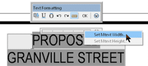
It is totally possible, though not at all intuitive. Here are the steps:
1) Make the multi-line attribute width very narrow, like 1mm.
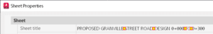
2) Edit the title property in the sheet set manager.
3) Place a space where you wish the line break to happen and place a non-breaking space where you actually want spaces. The red and yellow icons below indicate where the non-breaking spaces are.
You see, when there are non-breaking spaces, the text following it is forced to reside on the same line.
Alt+0160 to get a non-breaking space, hold down the ALT button while entering 0160 on your keyboard number pad. You MUST have a number pad; this will not work with the numbers on top of your keyboard.
Do you use targets to modify the width of a lane or sidewalk? Would you like to vary a daylight slope over a station range? Are you looking for a different way to handle driveway curb letdowns? If you said yes to any of these, the 23.2 update for Civil 3D has a new feature that can help. Read on.
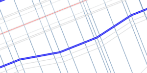
You probably know that geometry can be drawn, a polyline or alignment, and then defined as a target to change the width of a lane or sidewalk.
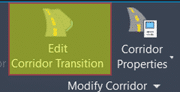
This works well, but there is a new option now. It’s called Corridor Transitions. Essentially, you can get the same result, but instead of drawing that geometry, the widths can be defined in a tabular format.
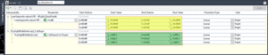
Select a corridor and choose Edit Corridor Transitions in the ribbon.
Enter values in the panorama that define the transition you need.
Click Apply.
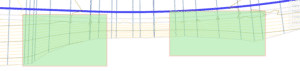
Here, the width parameter of the LaneSuperelevationAOR is being controlled by the values in yellow. There are 3 stations ranges that define where and how the transition happens. Also, the DaylightMultiIntercept slope parameter is being controlled by the values in green. It transitions from a 2:1 slope to a 1:1 slope between 4+80 to 5+60, then there are 2 other transition regions after that.
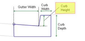
To define a driveway curb letdown, use the same procedure, except that the subassembly parameter that is varied would be the curb height. 3 transition regions will define a single letdown.
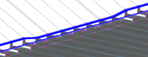
All these features are welcome, but two of them are great news to many, especially Civil 3D users. Specifically, the features related to point classification.
Notable changes are:
Scans are now imported and indexed in parallel, meaning faster imports.
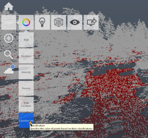
Clouds can be displayed using their classification if any exist in the imported file.
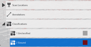
Classifications appear in the Project Explorer. These can be managed as needed. All points except, ground points, for example, can then be exported for use in other apps, like Civil 3D.
Unclassified points can be Automatically Classified. Scans must be structured, or the classification will fail.
Bluebeam’s dexterity as a construction technology makes it invaluable to the industry, but standardizing its tools and features to specific job roles or workflows makes it even more valuable.
Standardization is paramount in construction. Whether you’re a superintendent on a multibillion-dollar skyscraper project or an estimator on a mixed-use development, every industry player needs to abide by a set of standards to get the job done.
Using construction technology is no different. As digital collaboration tools continue to play an outsized role in the industry, it’s critical that those who are leading technology implementations customize the tools so workers can learn them quickly and apply them on the job effectively.
Perhaps no construction technology benefits more from standardization than Bluebeam. The tool’s pliability is one of its greatest strengths. Here’s how to apply standards to Bluebeam so you can get the most out of the technology.
Simplify what you see
Construction is a complex industry. Any given job may have more than 100 different types of roles, from the general contractor overseeing the production of a build, to the architects and engineers determining a project’s fine details, to the electrician carrying out those details.
Bluebeam is designed to help all of these people do their jobs better. Still, its capabilities are so robust that any first-time user might become overwhelmed. Therefore, it’s critical that, upon implementation, Bluebeam is customized with standards that are specific not just to each role but any particular workflows as well.
The best way to do this is to eliminate anything that’s unnecessary in Bluebeam’s interface. If you don’t need to create forms in Bluebeam, for example, scrap the icons and buttons to remove them from view. Repeat this with any other unneeded tools, panels or capabilities.
Create Custom Profiles, Tool Sets, Icons, Etc.
Revu, Bluebeam’s flagship PDF markup tool, has a seemingly endless amount of features. One way to completely customize Revu to better serve a job role or workflow is to save specific interface settings as a Profile, which can then be shared with other project colleagues.
Watch the video here https://youtu.be/RswYZRTXsVM
By creating custom Profiles, users can re-order and even turn off any of the interface’s panels and tools, ensuring that only the most used and relevant tools are in view. Users can do the same with the toolbars within Revu. Standardizing workspaces in Bluebeam with custom Profiles, and sharing those Profiles across teams, will go a long way toward simplifying the overall experience of using the technology.
Customization doesn’t stop with Profiles in Bluebeam. Markup tools—the symbols that are saved in the Tool Chest—can also be standardized as a custom tool set. Moreover, users can upload their own markup icons to standardize for use in a specific project or workflow.
Like with Profiles, implementation leaders should take advantage of such customization. From tool sets to specific markup icons, create a standardized experience in Bluebeam for your team that is as specific and simple as possible.
Review standards often
While establishing standards in Bluebeam is essential at the beginning of the tool’s implementation, it’s equally important that custom elements—from Profiles to tool sets—are reviewed and updated regularly.
Bluebeam is like a fine wine—it gets better with time. As knowledge of Bluebeam expands as people on your team continue to use it, it’s worthwhile to potentially integrate new tools and features as part of your customized standards.
Review these standards on an informal level every quarter, while larger, more robust standardization updates should happen once every six months to a year. Use these opportunities to gain feedback from users on which standards should be updated or eliminated.
The bottom line
Bluebeam’s versatility as a construction technology makes it invaluable to the industry. But with such flexibility comes the need to customize it for specific types of users and workflows. Failing to set standards when using Bluebeam—or any construction technology—risks slowing down the tool’s adoption and overall effectiveness over time.
A short article today. Click here for more the official documentation.
The Grading Optimization tool and Project Explorer are now available with a standalone license of Civil 3D. Previously, you needed to subscribe to the AEC Collection.
Starline Windows’ digital workflow on a connected cloud platform helps enable it to control its entire process, doing all its own assembly, manufacturing, construction, and installation. Courtesy of Starline Windows.
In Vancouver, Canada, window company Starline Windows was an early adopter of digital design and uses lean processes to deliver custom products.
The 2008 recession and COVID-19 pandemic both jumpstarted the company’s digital transformation to compete in a packed marketplace.
The result is a greener, more profitable, and more responsive business delivering more value to customers, partners, and employees.
Starline’s ongoing digital transformation has accelerated the design-to-delivery process by connecting data from various applications.
If buildings were bodies, the exterior would be the skin, blocking wind and rain while keeping everything inside warm and comfy. But in construction, vents, pipes, doors, and windows repeatedly puncture that outer layer. For a building to sustain the environment inside, those elements have to fit perfectly and seal seamlessly.
Defects that measure only millimeters become huge headaches if a window doesn’t quite meet spec. It may need to be trimmed onsite or reordered and replaced. Either way, it amounts to time lost and added expense. To get it right the first time, Vancouver, Canada–area window company Starline Windows has embraced digital design, making it the foundation for great industry relationships, profitable growth, and a more sustainable operating model. Starline has become a supplier of choice for many high-profile construction projects, collaborating effectively with internal and external partners.
Integration for Better Outcomes
Starline designs and manufactures architectural aluminum window systems for residential and commercial buildings. In business since the early 1970s, the company has delivered thousands of projects in its key California and Canadian (British Columbia and Alberta) markets. In fact, Starline Windows is responsible for making and installing the windows and doors in 25% of the high-rise buildings constructed during the past 50 years of the Vancouver, Canada, downtown core—the area most known for the city’s iconic skyline.
Starline’s array of window products includes punched, window-wall, curtain-wall, and balcony door. Unlike many manufacturing businesses that opted to outsource in the 1980s, Starline has stuck with a vertically integrated corporate structure in which most of its supply chain is company-owned, including state-of-the-art, fully automated manufacturing facilities.
“It’s a really special company,” says Catherine Walmsley, virtual construction manager at Starline. “We’re quite unique, and I think that comes down to not just what we do, but how we do it. We own our own supply chain. We do our own assembly and manufacturing. We have in-house IT support, and we do our own installation and construction.”
Starline Windows has made the windows and doors in about 25% of the high-rise buildings constructed in the past 50 years in Vancouver’s downtown core, such as the Modello (pictured) by Boffo Developments. Courtesy of Starline Windows.
When Starline takes on a job, “we work with our partners to meet their needs as well as our own,” Walmsley says. However, even with the level of control afforded by its integrated structure, the company still faces business challenges common to the envelope trades, including a lack of design collaboration with architects and contractors, poor visibility for field personnel when design revisions happen, and limited data sharing between the office and the field. A lack of cross-department collaboration can also get in the way of efficient logistics.
In a highly competitive market, working closely with project stakeholders to demonstrate value can be make-or-break. In its 2022 Pulse Report, Window + Door Magazine found that 62% of contractors were on the hunt for new window suppliers to protect the supply chain and keep up with customer requirements. Issues like flexibility, turnaround time, material availability, and pricing were among the top reasons cited for shopping around.
Traditional Structure, Modern Challenges
“When you’re working on a complicated project, you need to be able to work with others,” Walmsley says. “So it’s important for us to be able to understand the process as a whole.”
Improving end-to-end process clarity benefits every architecture, engineering, construction, and manufacturing business, but rising demand for custom designs makes this goal more challenging. As requirements become more tailored and less standard, better tracking and traceability across the product lifecycle is essential.
The efficiency of Starline Windows’ digital transformation helps make the company both more sustainable and more profitable. Courtesy of Starline Windows.
Working with architects closely at the outset and ensuring design commitments are being met from manufacturing to installation are necessary to meet custom requirements. The COVID-19 pandemic and its increase of remote working have compelled an industrywide rethink of how tighter collaboration and greater visibility can be delivered to clients.
But just as it decided early on to stick with a traditional business structure, Starline also became a digital early adopter. That’s put the company on the right footing to meet today’s challenges.
A Digital Early Adopter
“We do everything from design to manufacturing, installation, and even shipping,” Walmsley says. “That’s a lot of territory to cover, and anything you can do to virtualize construction information is a benefit.”
Starline recognized that issue as far back as the early 1980s, when it started the shift from paper drawings to computer assisted design (CAD).
Starline’s all-digital and cloud-connected design-to-delivery workflow makes it easier to deliver bespoke windows for large projects such as Civic Plaza, Surrey, British Columbia’s tallest building. Courtesy of Starline Windows.
“We were pretty early to embrace CAD,” Walmsley says. “We had an amazing IT guy, and once CAD went open source around 1985, we saw the opportunity to replace paper-based workflow and reuse all the data contained in hand drawings.”
Things really changed in the aftermath of the 2008 recession, when macro considerations forced the company to find new ways to rationalize costs and downsize—without sacrificing quality or delivery.
“We were always fans of lean operating principles, but after 2008, we had to go really lean and find ways to deliver the same number of projects with fewer people,” Walmsley says. “But we also had to enable the ones who stayed to work more efficiently. Our people in the field in the buildings were very attached to their pieces of paper, but when we put an iPad in their hands, it was a huge game-changer. Suddenly we could provide change paperwork on the fly without having to call FedEx and have a ream of paper delivered to the site.”
Along with digitized field operations, the company’s manufacturing facilities are almost completely automated. “Some manual processes remain, but they are few and far between at this point,” Walmsley says. “Most of our manufacturing assembly is now roboticized.”
Starline’s ongoing digital transformation has accelerated its design-to-delivery process by connecting data from Autodesk Fusion 360, Vault, Revit, Inventor, and the Autodesk Construction Cloud. Walmsley says those tools, which integrate information from multiple systems and generate 3D designs, help complete the digital operations picture.
They’ve made it easier to deliver on bespoke design needs for major projects such as Civic Plaza in Surrey, BC. It’s the city’s tallest building and some of its guitar-pick-shaped skylight windows set the bar high for Starline’s capabilities.
“We could do circular shapes, but we had never attempted something so custom,” Walmsley says of the buildings nonstandard skylights. “They are huge—8 feet—so it was just an incredible feat to be able to put it all together and to coordinate. The lead time was extensive, and it was very challenging to get them to the building and installed on time.”
The Civic Plaza’s guitar-pick-shaped skylight windows put Starline’s capabilities to the test. Courtesy of Starline Windows.
Sustainable Benefits
Doing more with less but still doing it better is digital’s core mission. Walmsley says that for Starline, it’s made business planning easier and improved quality control. “Today, I can pull data from Revit, from Inventor, from our ERP and inventory-control systems to track all of the various activities happening and give upper management the information they need. It all adds up so that we know how many windows we can produce, how close we are to reaching project commitments, and when our next sale is due.”
Going digital has also had green benefits. It’s dramatically reduced the reliance on paper, as well as the volume of toner and other printer consumables the company uses. There’s also much less physical waste for disposal because more accurate design and manufacturing means fewer deficiencies and less cutting and trimming at the building site.
When deficiencies do occur, they can be captured and tracked to avoid replicating the same mistakes.
Walmsley says the real test, however, is how well a digital tool helps Starline work more closely with clients, partners, and other stakeholders: “It’s not just about us. It has to be beneficial to the architect, to the developer, and to the customer. In the end, the biggest selling feature is knowing we’re delivering something that’s going to make the building sell, that’s going to make everyone’s life easier, and that’s going to make people want to work with us again.”