• AutoCAD 2021 is Here

    It’s that time of year again folks; Autodesk has released their flagship product in AutoCAD 2021.  Here is an excellent article explaining the new changes.  Below are the features that are close to this BLOG writer’s heart.

    Format

    There is no format change this year.  Excellent!

    Enhanced Commands

    Trim and Extend have new default behavior resulting in fewer clicks.
    Revision clouds are now their own object.  Including a new Arc Length property.

    The Break At Point command can now be repeated resulting in fewer clicks.
    Drawing version history comparison for files stored in cloud services such as OneDrive and DropBox.

    The block palette now contains a Library for blocks stored in cloud services or other folders.

    AutoLISP

    A brand new AutoLISP development interface which uses Visual Studio Code with a LISP extension.  Auto-complete functions and parentheses.


    Path of Travel update on Revit 2020.2

    Since my last post about the path of travel, Autodesk made a very useful update on the path of travel tool.

    The path of travel was calculated automatically by Revit picking the start and end point. Now we have the ability to add waypoints along the path of travel. This allows us to drag the points and adjust the path. You can also delete the waypoints to restore to default position.

    To activate the tool, simply select the path of travel. The tool will appear under the Modify| Path of Travel Lines. Select the Add Waypoint, click on the path of travel and drag it to adjust it. To delete it, select the Delete Waypoint and click on the point.

    Frame Generator End Caps in Inventor 2020

    In the 2020 release of Inventor, the Frame Generator Design Accelerator received a number of minor enhancements as well as one of significance that likely has users asking how they ever lived without it. You can now create and insert end caps to a frame member within Frame Generator.

    Here’s how:

    First; you must have the Custom Content Center Library installed in order to use this feature. Learn how to do that here. Once you have frame members ready for end caps, follow these steps to quickly create and add the components:

    (1) Select “Insert End Cap” on the Frame panel of the Design tab within your assembly;

    (2) Select the end faces of the members you wish to apply end caps to.

    (3) Choose the placement: Inset, or outward

    (4) Choose the profile style: Filleted, Chamfered, or Sharp corners

    (5) Enter the Chamfer/Fillet size (if applicable), Thickness, Inset (or Offset) distance & Rotation angle

    (6) Select the desired part properties, then OK (or “+” to add additional end caps for different tube profiles without exiting the property panel)

    (7) The end caps are created as members of the frame assembly and the file naming can be controlled in the same way (using “File Naming Defaults” in Application Options). Inventor recognizes identical members upon creation and reuses the end cap files where possible, rather than duplicating them.

    End caps can be edited or reused like frame members, using the right click menu in the model browser (“Edit with Frame Generator”)

    Finally, plan and profile sheets that update after design changes

    Plan production tools in Civil 3D are great for creating plan and profile sheets, but what about when the inevitable design changes come and you need to update your sheets? You either update them manually or recreate all new sheets. With CTC Software’s Sheet Generator, you can create plan and profile sheets that update after designs change, including refreshing of viewports, north arrows, matchlines, sheet names and numbers, sheet set data, and more. Sheet Generator provides better control on Profile Views, more flexible sheet management workflows, and easily dovetails with your company standards.

    For more click here

    Create custom legends and QTO with Data Wizard

    Tabling, legend creation and QTO workflows leave a lot to be desired in Civil 3D, forcing to use many different subpar tools, or worse, performing the work manually. With Data Wizard you can scan any number of drawings for AutoCAD and Civil 3D objects to generate legends, tables, QTOs, and more, all to company standards, and all automatically. When drawings change, refresh tables to automatically incorporate updates. Save out templates for quick recreation of custom tables and legends.


    For more click here

    Interested in tweaking an HSM (Inventor CAM, Fusion CAM, HSMWorks) post-processor yourself?

    The “SolidCAD Universal FANUC” post processor (free on our website) contains a large number of parameters that can be set on-the-fly through the “Post-Process” dialog, without needing to change anything inside the post-processor.

    If you require other changes, SolidCAD offers a post-processor modification service to adapt this post to your machine and to your best practices. If you wish to make changes yourself, you are free to do so. Indeed, the “SolidCAD Universal FANUC” post-processor and all the post-processors available on the HSM Post Library website are unlocked and open-source.

    The HSM Post Library is found here: https://cam.autodesk.com/hsmposts

    A post .cps post-processor file is merely a text file. It can be opened and edited in Notepad or any other text editor. There is unfortunately no user interface; changes must be made to the code in JavaScript language.

    However, the good news is that Autodesk publishes a free manual to guide you through the process, covering the basics of JavaScript and explaining the various sections of a post file. The manual can be downloaded here: https://cam.autodesk.com/posts/posts/guides/Post%20Processor%20Training%20Guide.pdf

    If you can’t find an answer in this 200-page guide, you can consult the vast archive of the HSM Post-Processor Forum, and even post your question on this very active forum. The forum is located here: https://forums.autodesk.com/t5/hsm-post-processor-forum/bd-p/218

    Curious about the hype around Autodesk’s HSM CAM?

    Hey CNC’ers!

    Curious about the hype around Autodesk’s HSM CAM? And now you’re looking for more information and possibly a demonstration? Well, you’ve come to the right place! SolidCAD is not only Canada’s biggest reseller of Autodesk manufacturing solutions, but also the only Canadian Autodesk reseller with a dedicated team of CAM specialists.

    HSM CAM is the comprehensive and powerful CNC programming add-on for Inventor (Inventor CAM – included with a subscription to the Product Design and Manufacturing Collection ), Fusion 360 (Fusion 360 Manufacturing – built into Fusion 360), and even SolidWorks (HSMWorks – included with a subscription to Fusion 360).

    Please visit our HSM CAM page to read about all the advantages of this integrated CAD/CAM solution and to find lots of technical resources: https://www.solidcad.ca/partner-products/hsm-cam/

    Also, try our SolidCAD universal milling post-processor, compatible with a wide variety of 3-axis, 4-axis, and 5-axis machines that accept FANUC-style G-code. This open-source post-processor generates nicely-formatted NC code, and is chock-full of features to make it as flexible as possible. These features include:

    • Safe restart feature after M00 program stops
    • Automatic date and time stamp function
    • Tool table feature in header
    • Operation name, tool name, and cycle time at top of each operation
    • Activation of accumulated pecking depth feature for G73-style drilling
    • Activation of the Manual NC code pass-through feature
    • Property to toggle between 3-axis / 4-axis / 5-axis configurations
    • Property to set maximal spindle speed
    • Property to toggle tool preload on/off
    • Property to toggle rigid tapping on/off
    • Property to assign an M-code for rigid tapping
    • Property to toggle between G54-G59 and G54.1 P1-P300 work offsets
    • Property to toggle between G28 and G53 retracts
    • Properties to set M-codes for 4th and 5th axis brake lock/unlock functions
    • Property to toggle on/off the output of rotary axis positions at every operation
    • Property to toggle on/off the output of M01 optional stops at tool changes
    • Property to toggle on/off automatic spindle gear changes
    • Property to set a spindle gear change crossover speed
    • Property to toggle between French and English for the output of comments and messages
    • Property to toggle on/off lowercase support for comments
    • Property to set the rapid rate used for operation time calculations
    • Property to toggle on/off the automatic creation of sub-programs for patterns
    • Property to toggle between 4 digit and 8-digit program IDs
    • Property to toggle on/off the output of the tool list in the program header
    • Property to toggle between relative or absolute coordinates for IJKs
    • Property to toggle between automatic tool changer or manual tool changes
    • Property to toggle between M30 and M99 for program termination
    • Property to toggle between returning to home or going to parking position at program end
    • Properties to set X- and Y-coordinates for parking position
    • Property to convert from feed expressed per min. to feed expressed per second
    • Property to inverse Z direction convention
    • Property to disable output of all coolant codes

    This post processor is available here: https://www.solidcad.ca/solidcad-generic-post-processors-download/

    AutoCAD FLATTEN

    AutoCAD has a command contained within the Express Tool named FLATTEN.  It is designed to remove any non-zero elevations from selected objects within a drawing.  It does an excellent job with this, but there is some behavior that may not be obvious to all users.  This command works very well with many objects such as TEXT, LINES, and some BLOCKS.  However, unexpected behavior results when flattening Dynamic and Annotative blocks, even blocks with embedded non-zero-elevation linework.

    Annotative Blocks:  For example, an annotative block with a name of Arrow, is inserted 3 times.  Regardless of the attached annotative scales, the result after the FLATTEN command will be 3 blocks with 3 different names; Arrow-flat-1, Arrow-flat-2, and Arrow-flat-3.  Further, they will no longer be annotative.

    Dynamic Blocks:  After the FLATTEN command, each dynamic block will no longer be dynamic and will become an “unnamed block” with a name similar to “*U63”.

    Blocks:  A typical block will FLATTEN adequately.  A block which contains elements which have non-zero elevations, will also flatten adequately.  Understand that the FLATTEN command will make changes to block definitions in this example to set all elevations to 0.

    So what can be done?  Here are two options.

    • Download and run a LISP command from this discussion group post.
    • Be selective when flattening.  Flatten objects which have no deleterious results afterwards.  The AutoCAD FILTER command can be configured to easily select compatible objects.  The filter can be saved for future use.


    Revit Data Corruption

    Let’s talk about data corruption in Revit. In this post I will look at these 4 points:

    1. File crashes before opening
    2. Crashes when opening a new view
    3. Looking for corrupt families
    4. Higher level investigation

    As always you should make sure you save a copy of your file for testing while trying to resolve corruption issues.

    File crashes before opening

    Sometimes a file cannot open because of a simple issue that can easily be overcome. Each of the following actions have the potential to get past a different issue. If your file crashes when you try to open it ask yourself:

    • Can the file be opened with or without audit checked?
    • Will the file open without the worksets loaded? Can I narrow it down to a specific workset that keeps the file from opening?
    • Can I open the file in a different build, or a newer version of Revit?
    • Sometimes new name allows you to bypass the issue, copy-paste file to new location
    • Isolate the file from the network save to a location where the links cannot be accessed.

    Crashes when opening a new view

    If your file crashes when you try to open or create new views, try these suggestions:

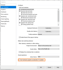
    • Turn off hardware acceleration and try each location one at a time.
    • Reset Revit settings
      • Customized settings are stored in the app data folder, when removed from this location the defaults are regenerated.
    • Repair the installation
      • This won’t change any user setting.
    • Open Revit without add-ins
      • Locate the following folder: C:\ProgramData\Autodesk\Revit\Addins\[Version].
      • Temporarily move the addin files from the folder above to another location.

    If any of these work for you take note, this is where the issue resides and you’ll want to know the exact cause whenever possible.

    Looking for Corrupt Families

    Sometimes the behavior you see in a file is caused by corrupt families follow this process to identify corrupt families.

    • Save a copy of the corrupt file
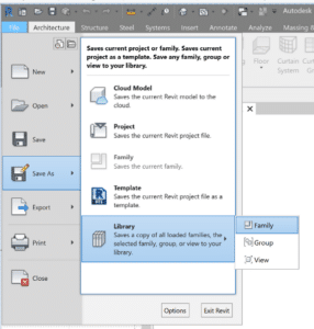
    • Open and save all families as a library, this process will fail when it reaches the 1st corrupt family.
    • Record the family named on the bottom left hand corner of the screen & delete the family and run again, repeat until the process completes successfully.
    • Open the original corrupt file and reload all the families on your list with versions that predate the corruption. If you’ don’t have a previous version of the family, you’ll need to recreate them.


    Higher level investigation & troubleshooting

    Many issues can also be fixed by returning to Revit’s original settings.  Try these steps one at a time, testing the file after each change.

    • Rename the .INI file (_old) which is in the AppData Roaming folder.
    • Rename App Data Folders (_old)
      • C:\Users\<username>\AppData\Local\Autodesk\Revit\Autodesk Revit 201x
      • C:\Users\<username>\AppData\Roaming\Autodesk\Revit\Autodesk Revit 201x
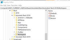
    • Rename Workspace in the registry editor

    When these folders/files don’t exist, they are recreated the next time the user opens Revit. Be sure rename and not remove these files/folders, as they will server as backups for the user original setting including keyboard shortcuts and font maps.

    Happy Reviting!

    Be sure to check my other videos in this series for more information.

    While you wait why not follow us @SolidCAD on Twitter, check out our other videos on YouTube, and see what our experts have to say on our BIM Blog!

    ___________________________________________________________________________________________________________________

    Additional Reading

    AKN: Revit – What Causes data Corruption

    AKN: Revit – Alternative Uninstall Directions

    Revit Family Creation: Family with Adjustable Built-in Label

    Usually Tags are added separate from the Components we place, but in certain situations the “tag” needs to be part of the family. To push this further occasionally a request is made for flexibility in the placement due to text overlap.

    This post explains how create a family with a built-in label with adjustable positioning.

    Prepare the Model Family to Receive the Label

    • Open the model family that requires the built-in label.
    • Create a vertical and a horizontal Reference Line to mark the center of the default label location.

    • Create a vertical and a horizontal Reference Plane offset slightly from the reference lines. These will be the anchors for the label. Both Reference Planes must be set as “Not a reference” for the grips to show properly in the project.

    • Dimension between the new horizontal references, and the between the new vertical references. These dimensions need to be assigned separate instance parameters. To allow the label to slide in the project.

    • Choose which existing reference planes you will Align and Lock your anchor Reference Planes to. I prefer to lock them to the planes the model uses as origins. The plane you lock to must be stationary (not controlled by an instance parameter), the label will not be able to cross the horizontal anchor plane.
    • Save the family.

    HINT: To make working in a complicated family simpler follow a few best practices.

    1. Set the origin planes, then pin them.
    2. Name reference planes clearly and remove temporary planes ASAP.
    3. Dimension to the reference planes, not geometry.
    4. Flex the parameters of the family before adding geometry.
    5. Geometry to be locked to reference plans after confirming the parameters work as expected.

    Create the Label Family

    • Using the Generic Annotation Family Template, create a new “label” family.
    • Place a label, you will be prompted to create/assign a parameter to the label.
    • Edit the label type properties, so the text size & style meets the company standards.
    • Save the label & load it into the model family you started with.

    Combining the Two Families

    • Place the label family near the geometry in the project.
    • Align the horizontal reference in the label to the horizontal Reference line, and lock.
    • Align the vertical reference in the label to the vertical Reference line, and lock.

    • Select the label and Edit Type, associate the Family Parameter for the Label to the Family Parameter in the host family which will control the text, often Description or Type Comments.

    • If you have chosen to have a visibility Parameter to control the Label Visibility, associate those parameters to one another as well.

    Using the Family

    • Save the Model Family and load into a blank project to test the flexibility of the label location.
    • Select the family, the grips for the label location will become visible. Slide then around in turn.

    NOTE: Look for unexpected changes to the geometry or the overall placement of the family, this indicate the need to change the anchor alignment.