• Achieving Super Results with Autodesk Fusion 360 and ExactFlat

    Achieving Super Results with Autodesk Fusion 360 and ExactFlat


    Recently SolidCAD’s own Hung Nguyen created an outstanding Iron Man mask for his son who was heading to Comic-Con. With a combination of the Autodesk Product Design and Manufacturing Collection and integrated apps from ExactFlat and Pepakura, the International Winner of the Fusion 360 Model of the Month was able to get the job done with little money and time. Hung began the process with ReCap Pro and converted human scan data to a 3D mesh model. He then refined the 3D model with ReMake and used Fusion 360 to prepare the model for production. After that, Hung created perfect flat patterns with ExactFlat Online software in a few short minutes.

    Since 3D modeling typically consist of “faces”, a piece creation step was taken to prepare the design for flattening since the faces may not align with the “pieces” that need to be cut. Hung used the ExactFlat Publisher Plugin for Fusion 360 to combine faces into pieces. The other key part of the process is optimizing the pattern for strain and sag which was done with Pre-Flatten tools in ExactFlat to generate the rough pattern. This optimization step provides a view of the pattern shape as well as highlighting areas of strain or sag in the pattern.  Knowing this before anything is cut is critical in saving time and materials.

    Once Hung had the patterns right, he used nesting software to optimize the material cost. He then generated CNC code using Fusion 360 CAM 2D profile cutting. The final step was to assemble all the parts of the custom-fit Ironman suit together, which was the perfect shape and size for his son.


    To learn more about Hung Nguyen, click here

    To learn more about Autodesk Product, click here


    Civil 3D 2018 and Large Surfaces

    Civil 3D 2018 and Large Surfaces

    If you have recently upgraded to Civil 3D 2017 or 2018 or are planning to AND you work with large surfaces (I’ll let you define what a large surface is) you’ll want to read this article!

    If you want to skip past all the history and get to the point, the short story is, 2017 and 2018 store the entire surface definition within DREF drawings and this affects performance. This option can be turned off.

    Most Civil 3D users know that a large surface should be created in one file and Data Referenced (DREF’d) to another file for use in such things as profiles and corridors. This helps reduce errors and improves performance.  2017 and  2018 are no different, but it contains a new feature which is meant to help another occasional user issue.

    When DREFs were introduced they were, and still are, susceptible to the source file being moved. If the source file is moved, not unlike an AutoCAD XREF, the source object cannot be found and the DREF drawing is empty.

    Civil 3D 2014 introduced a new feature where all Data References (except surfaces) are actually stored in the DREFd drawing file. If an alignment’s source DWG cannot be found, it’s no problem since the alignment actually lives in the DREFd file.  It’s still a DREF and it will still synchronize when the source file is found, but at least there’s something in the drawing and not a blank slate.  There is no option to turn this feature off, and you likely wouldn’t want to.

    Surfaces were not included with this feature because they can be very large and performance would suffer in the DREF file. They weren’t included, that is, until Civil 3D 2017.  Entire surface definitions are now stored in DREF files.  If the source file is lost, you still have your surface.  This is great for drawings containing few or small surfaces, but it can drastically affect performance for large surfaces.

    If your source surface is big enough to require an MMS file, there will be a second MMS file for the DREF drawing. These can be very large.  Not only does your drawing performance suffer, but now your hard disk must contain the additional MMS file.

    This option is ON by default and I’d leave it there if you primarily work with smallish surfaces. I’d turn it off if you typically work with big ones.  There are two options:

    1. Change the setting in your template (DWT) so that future drawings will have the option set as you wish.
    2. Change the option afterward for drawings containing existing surface DREFs.

    The DWT setting can be found in the Civil 3D Settings tab:

    If a surface has already been DREF’d, the option can be changed in the Prospector:2018 has been an excellent version and this feature is welcome to most, but beware of large surfaces.

    SolidCAD continues to strengthen its presence in the Quebec market with the acquisition of Consortech’s Autodesk business unit.

    TORONTO, ON, November 6, 2017 – SolidCAD, a leading Autodesk Platinum Partner and Canada’s premier technology solution and professional service provider announced today the strategic acquisition of Consortech’s Autodesk business unit. Located in Brossard, Quebec, Consortech has been assisting both design and data management professionals within the architecture, engineering, construction and geomatics industries for over 28 years. They are recognized as an Autodesk Gold Partner that helps clients analyze, recommend, implement and provide support and training on the best data management, design processes and solutions available. This acquisition is an exciting milestone for SolidCAD as they actively grow their team of professionals and expand their presence not only across Canada, but specifically in Quebec to address the needs of the local market.

    “We are extremely excited to welcome Consortech’s Autodesk business unit to SolidCAD and to have the opportunity to support and service their Autodesk customers in Quebec,” said Michael Kugan, President, SolidCAD. “As a national leader in the professional services industry, it is extremely important that we continue to offer the highest level of expert support, broad range of custom professional services and product expertise to our customers. This addition to our already extensive Autodesk solutions offering provides SolidCAD with the opportunity to continue to grow our professional services team and position ourselves as a market leader in Canada.”

    Consortech will leverage its strong presence in the GIS ETL business in Ontario and Quebec to pursue its expansion across Canada and United States. “This announcement follows the strategic decision to realign the organization on one business model primarily focused on consulting services for geospatial data management,” declared Mr. Rémy Pelletier, President and CEO of Consortech. “We have chosen SolidCAD due to their strong national presence, as well as their ability to tackle the challenges pertaining to Autodesk’s new business model. Our Autodesk clients will have the opportunity to work with a partner benefiting from an extensive experience in the architecture, engineering and construction industries. As for those Consortech employees, currently dedicated to Autodesk business, they will join the SolidCAD family and maintain the same high level of professionalism that has helped them serve the customer base we have built over the past 15 years as an Autodesk partner.”’

    Autodesk is a registered trademarks or trademarks of Autodesk, Inc., and/or its subsidiaries and/or affiliates in the USA and/or other countries.

    About Consortech

    Consortech is a major North American consultant in geospatial data automation and integration for public and private companies specialized in land and infrastructure management. Founded in 1989, this company offers consulting services to help harness the full potential of data by using advanced ETL technologies. Its FME and FME Server certified experts enable organizations to access reliable and high-quality information in order to make the best decisions for their community.  www.consortech.com

    Vehicle Tracking Update 2018.1

    Vehicle Tracking Update 2018.1

    Autodesk has clearly spent considerable resources developing this update.  There are many fixes and enhancements in this Vehicle Tracking 2018.1 update.  You will find information about the update here.  Click this link to view a recorded webinar.  The update can be installed with the Desktop App or by downloading it from Autodesk Account.

    There is one critical change that will affect all users.  There has been a mid-cycle format change for the vehicle tracking objects.  Don’t worry, the drawing format is not changing, just the vehicle tracking objects; roundabouts, swept paths etc.  What this means is if a drawing is saved with 2018.1 and then opened in 2018 without the update, the vehicle tracking objects will appear as proxy objects and therefore not editable.  All users’ workstations must be updated concurrently.

    Since grip-editing is very popular method for editing vehicle tracking objects, it is recommended to install the Map 3D hotfix previously blogged.

    A brief look at the changes:

    • Object format change.
    • Get units from the drawing.
    • Parking tool enhancements.
    • The majority of the enhancements are related to roundabouts and their corridors.
      • Better baseline and region development.
      • Slip lanes are now 3-dimensional.
      • Fixed overlapping corridor links.
    • Defect fixes.


    Civil 3D Update 2018.1

    Civil 3D Update 2018.1

    Autodesk has released the latest update for its Civil 3D 2018 application.  You will find information about the update here.  Click this link to view a recorded webinar.  The update can be installed with the Desktop App or by downloading it from Autodesk Account.

    A brief look at the changes:

    • New corridor rehab workflows and subassemblies.
    • Crossings and projections improvements.
    • The new Infrastructure Parts Editor introduced with Infraworks 2018 is now supported in Civil 3D.
    • Reference templates improvements.
    • Defect fixes.


    AutoCAD Update 2018.1

    AutoCAD Update 2018.1

    Autodesk has released the latest update for its AutoCAD 2018 application.  You will find information about the update here.  The update can be installed with the Desktop App or by downloading it from Autodesk Account.

    A brief look at the changes:

    • Xref layers override improvements.
    • View and viewport improvements.  Please note that if this update is applied to Civil 3D, these improvements are available, but do not appear in the ribbon.  See this document for details.
    • High resolution monitor support.
    • Defect fixes.


    Revit Courses are now CanBIM Certified!

    NEWS UPDATE: SolidCAD Now Offers courses that are CanBIM Certified!

    At last week’s CanBIM meeting in Toronto, SolidCAD recently announced that they are CanBIM certified.

    You can now take Revit courses that are recognized by the CanBIM Foundations. To learn more about which courses this includes, visit:

    https://www.solidcad.ca/services/training/

    Civil 3D / Map 3D Hotfix

    Civil 3D / Map 3D Hotfix

    Autodesk has release a new hotfix for Civil 3D and map 3D 2018.  The issue occurs when grip-editing an AutoCAD arc and some other objects.  The position of the mouse is different from the position of the grabbed vertex. 

    SolidCAD

    The issue occurs when you move the vertex a second time within the same selection and only for AutoCAD Objects.  There are two other problems this hotfix addresses.

    Click here to for more information and to download the hotfix.  Download the ZIP file and be sure to read the “hotfix readme.txt” file for installation instructions.


    Bluebeam Revu 2017 Updates

    Bluebeam Revu 2017 Updates

    Bluebeam has released Updates 1 and 2 for its Revu 2017 lineup.  See Bluebeam’s Release Notes for more information.

    As usual, there are fixes for defects and some new functionality.  Notable items include:

    • Compatibility with Autodesk AutoCAD 2018.
    • Compatibility with Autodesk Navisworks.
    • Compatibility with Autodesk Revit 2018. (CAD and eXtreme only)

    Only Update 2 requires installation as it includes all of the fixes and enhancements from Update 1.  To apply the update, there are two options:

    1. If you already have Revu 2017 installed, simply launch Revu and Click Help> Product Updates.  The correct installation link will be provided.
    2. If you do not have Revu 2017 installed, download the full Revu installer from the Bluebeam Updates page.


    Jenoptik

    Success Stories

    Jenoptik

    © Copyright Jenoptik Automotive North America

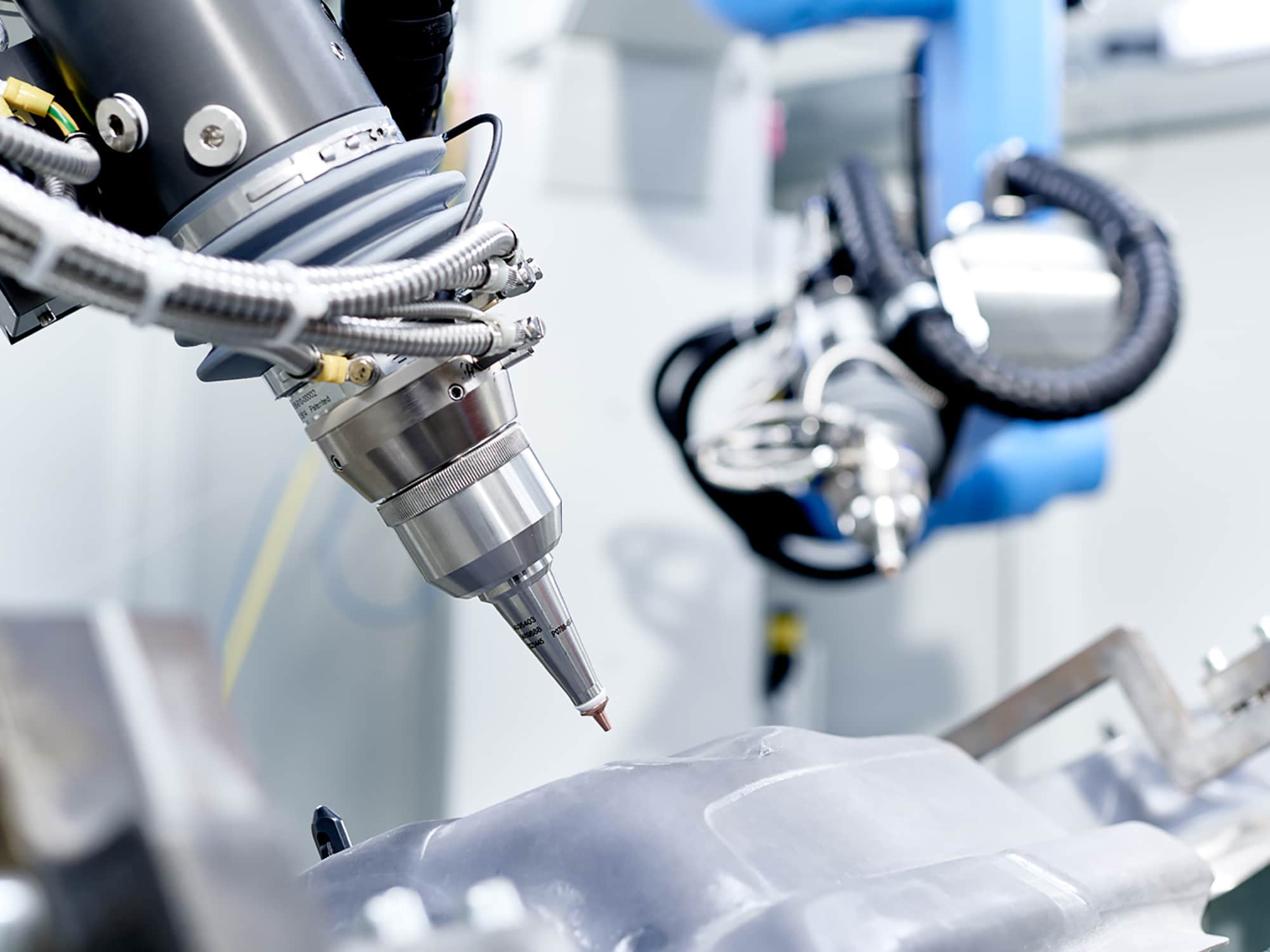
    Jenoptik is an integrated photonics group that operates globally. Jenoptik divides its activities into three segments: Optics & Life Science, Mobility and Defense & Civil Systems. These segments are, in turn, composed of five divisions: Optical Systems, Healthcare & Industry, Automotive, Traffic Solutions and Defense & Civil Systems.

    Jenoptik services customers primarily in the semiconductor equipment, automotive and automotive supplier, medical technology, defense and security as well as the aviation industries; offering services in strategic corporate development and innovation management.

    Jenoptik is concentrated on a variety of different industries, however a portion of their business is dedicated to the automotive industry through developing and constructing industrial measuring technology that can be used to monitor and optimize production processes.

    Project Profile

    Challenge

    As a leading manufacturer and system supplier, Jenoptik depends on exporting a parts list to Excel which is used internally by both the purchasing and manufacturing departments of the company. Prior to working with SolidCAD, Jenoptik identified that the original export tool available in Inventor would export Excel files that required a significant amount of manual editing and formatting by an employee. Editing often included: (a) moving all components of subassembly to their own tab, (b) sorting all components on a tab by their part number, and (c) adding project information header to all tabs. On average, formatting this data would take anywhere between four to eight hours for each assembly file which was both time consuming and subject to errors.

    Solution

    After identifying the issue, Jenoptik turned to SolidCAD in need of a solution that would streamline their process. SolidCAD provided Jenoptik with a workflow assessment that would investigate their current process, provide a detailed analysis and consult them with a solution that would automate the process and easily export Excel files with no manual editing.

    After a full assessment of the issue, SolidCAD’s development team customized Jenoptik’s Inventor software with an add-in to automatically generate a complete Excel parts list of their model assemblies, formatted in accordance with downstream requirements.

    Results
    • The Excel parts list was exported into a document that was correctly formatted to the company’s requirements, eliminating any possible errors that would be caused by users having to manually edit the default export.
    • With the integration of this automation, the Excel file is now created instantaneously, saving an average of six hours per assembly that would be spent on manually editing the Excel file.

    Testimonial

    When we were transitioning our software to Autodesk Inventor, SolidCAD handled the implementation of Vault Professional. After an extremely smooth launch of our system along with informative training, we had a unique request for the SolidCAD team to write a custom program that would automate some of our processes.

    The staff that we worked with were very knowledgeable and their use of web based communication software for meetings and testing was a huge convenience. The results we received from SolidCAD were always above expectations. I would highly recommend them to anyone looking for technical expertise for their software products.

    – Ronald Buchholz, Mechanical Engineer Leader, Jenoptik Automotive

    Products & Services Used

    Similar Projects

    D-Wave

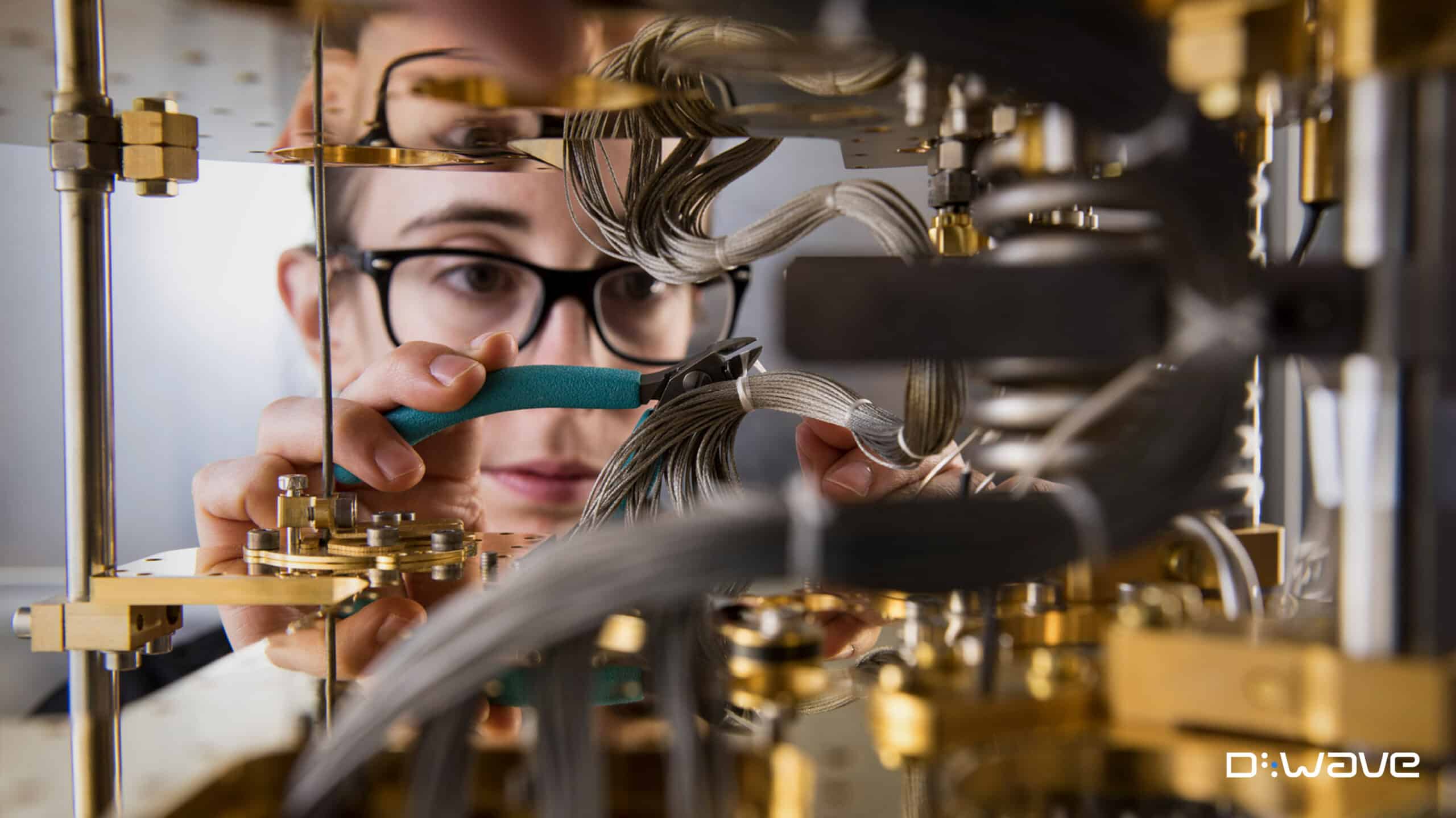
    D-Wave Quantum Inc. (D-Wave) is the leader in the development and delivery of quantum computing systems, software, and services. It is the only quantum computing company building both annealing and gate model quantum computers and…

    3D-P

    3D-P consists of a team of mining and positioning technology experts. It was created to bring innovative thinking and new technologies to the mining industry. They have since evolved to bring this approach to several…

    Starline Windows

    Starline Windows is an industry leader in the design and manufacturing of architectural aluminum window systems, as well as residential vinyl windows and doors for over 50 years. They have completed thousands of contracts and…