• Civil 3D Pressure Pipes

    Civil 3D 2021.1 introduced several new features including a new compass when creating a pipe run.  This is excellent news, but depending on your modeling requirements, it can cause an issue if you leave in a new setting.

    In the examples below, the parts list has no bends, and they are not needed for this design.  The pipe runs as required to be drawn like a polyline.  While working with a customer, I ran into this issue, but I could not find the solution, and surprisingly, neither could Autodesk.  Thanks to my esteemed colleague, Colin Gaudet for discovering what turns out to be a very simple solution.

    2021.0

    This is the behavior from 2021.0 and it is the expected behavior.


    2021.1

    This is the behavior after installing 2021.1.  The compass indicates that there are no bends and it will not allow any angle to be drawn, only a straight line.


    The Setting

    There is a new setting to allow pipe runs to be “snapped” to known bend angles.  Turn off the new setting to return to the expected behavior when there are no bends.  The compass remains, but it now allows any angle to be drawn.

    Autodesk Fusion 360 & Metallic Strip Animal Sculptures – Part 1

    Part 1

    I love sculptures and can spend hours at museums that devoted to sculpture. I also love structural Engineering and structural sculptures. Running into Artist Sung Hoon Kang‘s stunning animal sculptures that embody the movement, speed, and chaotic energy of the wind, fascinated me. You can take a look of his work here: Metallic Strip Animal Sculptures Radiate the Energetic Flow of Wind:  https://mymodernmet.com/kang-sung-hoon-sculptures/ Sung Hoon Kang‘s works got into in my head and made me think of how I can use Autodesk’s products such as Fusion 360 or 3DS Max to create/model these sculptures. I know Fusion 360 can combine organic shapes modelling, mechanical design, and manufacturing in one comprehensive package, but can it be used to create/model these kind of art works?

    The question stayed in my head until I found a possible solution by combining Fusion 360 and 3DS MAX. After finding the approach and workflow, I created the concept models of two metallic strip animal sculptures of a dog and a horse, and posted them on Fusion 360 Gallery. You can find and download my two metallic strip animal sculptures here:

    https://gallery.autodesk.com/projects/141060/fusion-360-for-art-work—-horse-metal-strips

    https://gallery.autodesk.com/projects/141004/fusion-360-for-art-work—dog-metal-strips

    Believe it or not, once you find a good workflow between 3DS MAX and Fusion 360, You can create these animal sculptures in 20 minutes or less.

    Here is how:

    Step 1Understanding Fusion 360 Freeform Tools

    You should know that Fusion 360 is not just an awesome freeform modeler; it is also a parametric modeler. Fusion T-Splines are a combination of NURBS and Subdivision modelling that was developed in 2003.The T-splines company was bought by Autodesk and was built into Autodesk’s Fusion 360. The T-Splines subdivision surface technology in the Freeform toolset make it easy to create completely smooth, curvature continuous, ‘Watertight’ NURBS surface models, that you can convert to Solid models.

    Fusion 360 Freeform tools are very helpful when you want to create an organic surface without having to spend lot of time planning and executing individual surface patches. T-spline surfaces are simple and intuitive, and it is really easy to iterate through a number of different options.

    Step 2Understanding 3DS MAX Polygon modeling

    Polygon modeling is more common with game design than any other modeling technique as the very specific control over individual polygons allows for extreme optimization. Usually, the modeler begins with one of the 3ds max primitives, and using such tools as bevel and extrude, adds detail to and refines the model.

    Fusion 360 loves Polygon modeling objects and it can quickly convert those objects into solids for you if needed.

    There are two kinds of mesh that you can import into Fusion 360; however, only mesh that came from Polygon objects can be converted to solids.

    To covert triangulated mesh to solid, it needs to be converted to Editable Poly before inserting into Fusion 360. These are the steps:

    • Import triangulated mesh into 3DS Max
    • Apply Subdivide (WSM) with “Display Subdivision” turn OFF
    • Use “Collapse To” to Collapse mesh
    • Turn Collapse mesh to Poly mesh
    • Apply “Quadrify All”.

    Step 3Understanding 3DS MAX Particle Flow

    Particle Flow is a versatile, powerful particle system for 3ds Max. It employs an event-driven model, using a special dialog called Particle View. In Particle View, you combine individual operators that describe particle properties such as shape, speed, direction, and rotation over a period of time into groups called events. Each operator provides a set of parameters, many of which you can animate to change particle behavior during the event. As the event transpires, Particle Flow continually evaluates each operator in the list and updates the particle system accordingly.

    Particle Flow provides several tools for determining where in the system particles currently reside, including the ability to change particle color and shape on an event-by-event basis. You can also easily enable and disable actions and events and determine the number of particles in each event. To speed up checking particle activity at different times during the animation, you can cache particle motion in memory. Using these tools, plus the ability to create custom actions with scripting, you can create particle systems of a level of sophistication previously unachievable.

    To create a Particle Flow, you need to place a PF Source and assign the PF source to an object. I used a dog model as an example to illustrate the use of PF source in this GIF image.

    Step 4Saving Particle Flow trails and Export them to AutoCAD

    You can make Particle Flow to generate animated Splines and save Particle trails. The animated Splines can be exported to AutoCAD format to be used for creating structural model or Poly mesh that will be turned into solids using Fusion 360.

    Step 5Creating Metallic strips from exported AutoCAD file

    The AutoCAD file can now be imported back into 3DS MAX. You can turn all the splines into Polymesh by simply turn on the ‘Enable in Viewport’ under Rendering option. In my example, I chose “Rectangular” option with Length =15mm and Width = 3mm

    At this stage, the model may require some modification for different strip thickness or clean up according to the artist’s design. Whenever you are ready, you can then export the entire MAX model out as a OBJ format to bring into Fusion 360 for fabrication.

    All Splines with rendering thickness property can now exported to OBJ format for Fusion 360 to convert to solids.

    Step 6Creating Metallic strips and complete the model in Fusion

    This step is very simple. There are various Insert commands you can use to insert other file formats. These options insert data into a current Fusion 360 design rather than opening the existing Mesh (STL or OBJ format), SVG, or DXF file. Refer to the following links for more information about inserting meshes, DXF, and SVG files into Fusion 360 designs: How to insert a mesh body into Fusion 360

    The next step is converting a mesh body to a b-rep or t-spline body in Fusion 360, the current limit for number of mesh elements is roughly 10,000. Meshes with greater than 10,000 elements will cause the performance of Fusion 360 to suffer and Fusion 360 may not be able to convert them to solid bodies.

    On my next blog, I will discuss and share with you some tips and tricks on how to convert mesh body to a b-rep or t-spline body in Fusion 360.

    You can also find me on AU 2020 by following this link and search for ‘Hung Nguyen’

    Until next time…

    Autodesk Desktop Connector and Sheet Sets

    An update to the Desktop Connector as made available on August 11, 2020.  Here is the relevant Autodesk document.

    If you’re a Sheet Set user who also uses BIM 360, this update is for you.  In addition to other resolved issues, the main feature in this update is that Sheet Set DST files are now recognized.  When a DST file is uploaded via the Desktop Connector, any drawings contained therein and their references are all uploaded.  When a DST is opened in AutoCAD, drawings will be synchronized locally.

    AutoCAD 2021.1 Update

    Autodesk has released the first update for AutoCAD 2021.  Find official documentation here.  Here are some highlights:

    • Blocks palette:
        • There is a new Favorites tab.
        • Block can be copied from other tabs to the new Favorites tab.
        • Blocks synchronized in the cloud can become accessible across multiple devices.
        • You can better manage your synchronization settings in the Blocks palette now.
        • Insert a DWG into the current file without it being added to the Libraries tab.
        • New variable and setting in Options: BLOCKSYNCFOLDER – Sets the path where the recent and favorite blocks are stored.
    • In the AutoCAD web app, click Open in Desktop to open the drawing in AutoCAD or AutoCAD LT desktop.  A plug-in must be installed.

    Tons of new goodies for Fusion 360 CAM

    Since I last wrote here, there have been big, big changes to Fusion CAM (excuse me: “Fusion Manufacturing”). These changes range from completely new (and it needs to be said, very useful) machining strategies, to significant progress in the implementation of probing technology, to new love for turning, and to subtle but much-appreciated improvements to the user-interface.

    The biggest changes are contained within the Manufacturing Extension, a new subscription add-on for Fusion CAM. The idea is that while Fusion CAM (and Inventor CAM and HSMWorks, for that matter) is a modern and very competent CNC programming solution that can make short work of most jobs at a VERY attractive price, there are some customers that require still more power and that are willing to pay a little extra for it. Mold makers are a good example. In the past, the limited multi-axis toolpaths of Fusion CAM did not quite meet their needs. With the new Steep-and-Shallow strategy as well as toolpath trimming / direct editing (both technologies gifted from PowerMill), that has all changed. The Manufacturing Extension also opens the door to surface inspection and on-machine verification, a very hot button for anyone trying to increase efficiencies and get an advantage. Throw in automatic hole recognition technology (thanks, FeatureCAM) and a new Rotary multi-axis 3D milling strategy (this one is all Autodesk), and there is something for everybody. How much for these new goodies? 125 Cloud Credits ($125 USD) per month, month-to-month.

    And those other improvements? How about a new tool library interface? The old one definitely was a little clunky. And for those of you who make extensive use of user-templates to capture their best practices (why isn’t everybody?), how about a new interface that will allow you to sort and better manage everything?

    I haven’t talked about turning yet… It can be said that while Fusion CAM  / HSM CAM has traditionally been a competent turning solution, most of the R&D over the years has gone into making it a premier milling solution. But a dedicated turning team has now been brought into the development team, and turning is now getting the love it has always deserved. In my next blog, I’ll list all the recent changes (it’s a very long list of small but significant changes). What’s more, we are promised many more such improvements throughout the year, including something called Adaptive Turning that sounds very promising.

    Please note that the Manufacturing Extension is free to use right now through June 2020. So, by all means, give it a spin! Several of the other new features are available through the preview mode: just activate what you want under Preview Features in your Preferences; everything is quite stable.

    Now, it is quite apparent that Autodesk is turning Fusion into its premier CAM solution. That’s great news and we welcome all the improvements to an already-great CAM. However, if you are a user of Inventor CAM (or HSMWorks), don’t hold your breath for things like Steep-and-Shallow. Instead, Autodesk would rather you fire up the Fusion 360 entitlement included with your CAM. And to make it easier to use two platforms in parallel, recent changes now allow Fusion to play extremely well with Inventor and even SolidWorks.

    CTC 2021 Revit Product Updates!

    CTC Software was actively preparing to release updates to our AEC tools for Revit 2021. This release took place on May 4th and affected all of our AEC offerings. HIVE has undergone a massive update, streamlining all aspects of user interaction and management. Our software suites have all been built to work on the new Autodesk 2021 platforms, and the SuperDoor Configurator and Casework Configurator content packs have been upgraded for 2021 as well.  All of these tools will continue to support the 2017 versions of Autodesk products and newer, so they will also fit into your workflows for any version from the last 4 years.  Additionally, the Mechanical Electrical Plumbing Productivity Pack content files have been upgraded to 2019, containing hundreds of updated families and a lot of new features and improved workflows.  These tools are purpose-built to support your entire workflow from beginning to end, putting the right tools in the right hands so all team members gain efficiencies every day.

    Contact CTC or one of our partners for more information about the 2021 updates to our tools!

    HIVE

    HIVE specifically has had major changes to the user interface of the content management system (CMS).  Many of you have provided feedback after extensively using the currently released HIVE system.  We listened!  The new HIVE has a major facelift, and the HIVE management portal on the web has been overhauled to make management easier, and to provide you with analytics for organization-wide use of CTC tools, project performance metrics and insights into how your teams are searching for content in the CMS.  As always, we strive to develop our tools alongside you, so you and your teams can work efficiently.  Feel free to share your experiences and ideas for how we can continue to improve.
    The other productivity tools in the software suites are all updated to work on the Autodesk 2021 platforms as well. This year we have decided to make sure that we support 5 version of Autodesk products, since we know many of our clients have projects with long lifecycles.  While Autodesk may not officially support 2017, we felt that we should continue to make our tools available for that release since some of you have let us know that your projects are still being managed in that version.  This new 2021 release of our tools will have the ability to communicate with the HIVE management portal so you can have a better understanding of the return on your investment this next year.

    CTC has 3 major Revit-based content packs.  The two that install into the ribbon are the SuperDoor Configurator and the Casework Configurator.  These, like our other suites, will be supported on Revit 2017-2021.  The other content pack, the Mechanical Electrical Plumbing Productivity Pack (MEPPP), has been heavily updated in its latest version. It will be supported on Revit 2019-2021 with the actual content delivered in Revit 2019 format.  We made this choice since most of the projects starting fresh in your firms will be on 2019 and later.  We did not see value in building on older versions, as existing projects in production do not see huge benefits in transitioning standards mid-production.  This MEPPP update has seen further standardization of the parameters used to help align our pack with metric users.  The first release will be in Imperial units of measure, but a metric pack will be coming soon.  This release saw heavy formula updates and further removal of unit dependencies.  The lighting fixtures, electrical equipment and mechanical equipment have seen major updates, improving face-based and level-based hosting in a single family, and general ease of use.  Many other categories have been touched as well, to ensure a uniform workflow and general consistent use.

    As always, we encourage you to contact us or our partners for more information on these workflow-improving tools.

    In the United States you can contact Applied Technology Group (ATG) at sales@ATGUSA.com. If you are are based in Canada, please contact:

    Mughees Altaf
    Account Manager — AEC Productivity Tools
    mughees.altaf@solidcad.ca 

    This article was created by CTC Software

    Sharing is Caring

    In todays manufacturing world there is a bigger demand on sharing data with all stakeholders outside your company.  This could be your supplier, buyer, manufacturing team and they could require viewing the drawing to the 3D model that you create.  Using Autodesk Vault you can created a shared view for your outside stakeholders and value chain.  Autodesk provides this as a free viewer, markup and comments, all they would need to do is sign up for a free Autodesk account.  Also Share View is a great tool to use internally as well to do digital markups and collaboration outside the engineering department.

    To use Share View simply log into Autodesk Vault and find the model or drawing you would like to share and right click and select Share View:

    You may be prompted to login using your Autodesk account, once you have logged in the Create a Shared View dialog box will prompt you to enter a name:

    Enter the name you would like and then click on Share, and it will start to process the shared view.

    Once complete a Share View Complete Dialog will display that it was uploaded successfully and it will give you a copy link and view in browser option.

    Copy Link – This is the link you can email to your stakeholders for them to open and view online.

    View in Browser – this will open the shared view in your browser for you to view.

    Clicking on View in Brower it will launch the Share View online:

    This view will only be available for 30 days on Autodesk Viewer.  Only users who are invited though the link or when selecting share will have access to the model or drawing.

    Once singed in users can markup, add comments and when clicking on share, it will send the users in Vault a notification that someone has made a comment on the drawing.

    To make a comment simply select comments to type a comment directly.  Anytime you click on Markup the markup changes will be saved on the comments tab when you select Post.


    In Vault client to view the comments or markups make sure that Shared Views Panel is turned on.  If not turned on simply go to View > Shared Views and make sure there is a check mark beside Shared Views:

    In the Shared Views panel the comments and markups will be shown:

    To make a comment back simply click on Reply and it will take you back to the Autodesk Viewer to continue the collaboration between your company and stakeholders.

    As you can see getting data to correct users at a timey manor is critical in todays business.  Autodesk Vault Professional and Shared Views enables you to connect the value chain and make sure everyone has the data they need.  Also, Autodesk viewer is not just limited to Inventor or AutoCAD drawings and models if you go directly to viewer.autodesk.com you can sign into your account and upload the following files for collaboration:


    Remember Sharing is Caring and happy collaborating!!

    AutoCAD and Bluebeam

    Many users create PDF files from AutoCAD products as PDF seems to be the standard digital format.  There are three issues you may run into and some settings to consider if you use Bluebeam Revu as well as AutoCAD.
    Viewports


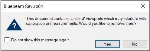
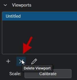
    First, you may see this message when opening PDF files using Bluebeam Revu (not the free viewer) which were created from AutoCAD using Autodesk’s DWG to PDF print driver.  These “viewports” are artifacts contained within the PDF file to which Bluebeam Revu alerts you when you open a file containing them.  ALWAYS say yes to removing these artifacts.  If you don’t, they will very likely affect the accuracy of any measurements you make in Revu.  If you skip past this message without selecting Yes, the viewports can be removed from the PDF in Revu’s measurement panel.


    Why do they exist in the first place?  It seems to be an issue with Autodesk’s DWG to PDF.pc3 file.  PDF’s created using Bluebeam’s PDF printer do not contain these anomalies.  Here is an Autodesk  discussion group thread discussing these viewports.  Interestingly, it indicates that these viewports can cause an issue when measuring using Adobe Pro, but there appears not to be a solution there, where Revu does indeed catch the existence of them.

    Searchable Text and SHX Fonts

    The second issue is searchable text.  Many AutoCAD users still use Autodesk SHX fonts.  There are several reasons to avoid using SHX fonts; not the least of which is that when a PDF is created containing them, that text will not be searchable when opened in any PDF reader software.  If you want your recipient to be able to search text, and you very likely should, do not use SHX fonts in AutoCAD.  Use a True Type font, such as Arial instead.  This is with one exception.  With Bluebeam Revu, SHX text is in fact searchable, but you must enable “Search Markups”.  More detail about this I the section below “Odd Markups”.

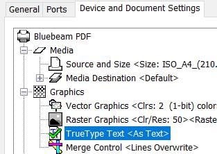
    If you’re a Bluebeam Revu user with the CAD version or better, and you prefer to use its PDF print driver instead of Autodesk’s, there is an option to enable SHX fonts as outlined in this article.  Better, do use a True Type font as mentioned above, but there is one more setting you must enable.  A PC3 file must be created using the Bluebeam print driver and then this option set in the printer properties in AutoCAD.  It defaults to TrueType as graphics and your text will not be searchable if it’s not changed.

    Odd Markups in Revu


    Lastly, using Bluebeam Revu (not the free viewer) to open a PDF created by AutoCAD using its DWG to PDF printer, you may see “markups” already contained in the PDF.  There will be one markup for each text object in the file, indicated by the AutoCAD SHX Text author.  That adds up to a lot of markups if it’s a file with many text objects.  This can affect the performance of the file within Revu and they will definitely be in the way when creating normal markups.  These markups are only required if you need to search SHX text; they cannot be deleted with Revu tools.  They can be Flattened in Revu prior to adding your own usual markups, or they can simply be filtered out if you don’t wish to see them.  Don’t worry, the text in the PDF will not disappear.  I do not have access to Adobe Pro to see if this is an issue there as well.

    These “markups” are created when printing from AutoCAD using the DWG to PDF driver and it is an Autodesk feature.  In AutoCAD, there is a variable named PDFSHX.  Turned on, a value of 1, enables these “markups” in the PDF file which results in searchable text.  Turning it off will result in no “markups” and non-searchable SHX text.  Here is an Autodesk document outlining this feature.  SHX text may or may not be searchable depending on the PDF reader in use.  For example, the Bluebeam Revu free viewer cannot search SHX text, but the paid version can.

    This issue does not occur with PDFs created in AutoCAD using Bluebeam’s printer driver.

    Dynamo for Autodesk Fusion 360 – Made Simple

    Dynamo Studio is typically associated with Revit; however, it offers a fantastic platform for algorithmic-driven design and easy parameter manipulation in Fusion 360. It also features great T-spline and surface support for complex geometry creation, for those wishing to bring a degree of parametric control to their surfacing with ease.

    The add-in supports a bi-directional data exchange between Fusion 360 and Dynamo Studio, allowing users to create visual logic for Fusion 360 parameters update. It can be downloaded here: https://apps.autodesk.com/FUSION/en/Detail/Index?id=74731490955641349&appLang=en&os=Win64

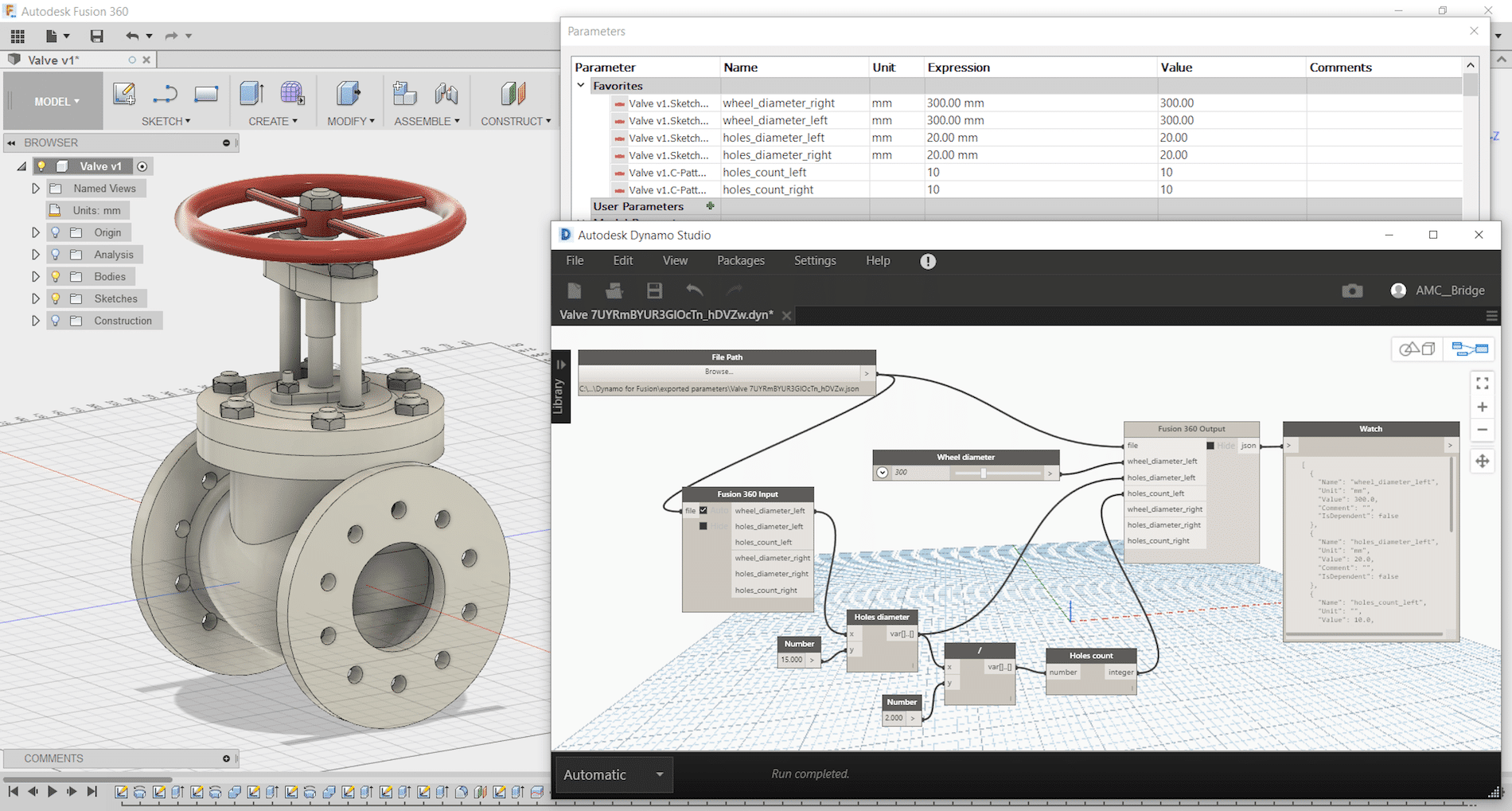
    It provides an ability to use a visual editor environment to modify Fusion 360 model parameters, view and use them in complex logical graphs. Fusion 360 parameters will be automatically updated from Dynamo Studio using custom input and output nodes.
    Dynamo for Fusion 360 Supports Dynamo Studio 2017 version: 1.1 – 1.3.

    The benefits of using Dynamo with Fusion 360 are:

    • Very complex and rapidly reconfigurable T-Spline surfacing is
    • Parameter driven components can be modified live using sliders to adjust
    • Parameter driven components can have logic integrated to link different parameters and make automatic adjustments according to conditional
    • Parameter driven assemblies can be modified live and can adapt if setup
    • Parameter driven assemblies can have logic integrated to link parameters from different components to respond to changing geometry according to conditional

    One of Dynamo – Fusion 360 Workflows is called “Synchronous workflow”. It is directly manipulating parameters listed in the parameter table in Fusion 360. This can enable rapid reconfiguration of assemblies and components by using sliders, or logic can be incorporated to describe relationships between geometry. If you have not tried, here are some simple steps to try:

     Step 1: Create a simple Fusion part with some name parameters as shown:

    Step 2: Save and name the part as “Dynamo-Fusion”

    Step 3: Go to Tools -> DYNAMO FOR FUSION to run Dynamo


    Dynamo will create a same name parameter file with extension “.json” that contains all extracted parameters from Fusion 360 part and stored under:  C:\Users\ (your username) \AppData\Roaming\Autodesk\Autodesk Fusion 360\API\AddIns\Dynamo for Fusion\exported parameters\

    Step 4: In Dynamo’s search bar, search for “output” and insert “Fusion 360 Output” node. Repeat search for “Slider” and insert “Number Slider” node.


    Step 5:
    In Dynamo, connect File Path to “Fusion 360 Output” and “Number Slider” to any parameter and set Min, Max and Step. Use the slider to size or adjust the features.


    If you would like to manipulate other parameters, then just add more sliders. Simply select the slider node and use Ctrl+C to copy and Ctrl+V to paste it. After that you can customise each slider values (Max, Min, Step) and connect it to any of the parameters and watch the part update. You can even connect a slider to more than one parameter (i.e. to make a square cut).

    Using Dynamo with Fusion360 can be fun and simple. Try it and have fun with Dynamo for Fusion 360.

    Civil 3D 2021 is Here

    It’s that time of year again folks; Autodesk has released their flagship Civil Engineering product in Civil 3D  2021.  Here is an Autodesk article explaining the new changes.  Here are my favorites from this release.

    Format

    There is no format change this year.  Excellent!  You may share your Civil 3D files with users back to 2018.

    Pressure Networks

    There has been significant development to this feature.  If you have not been using pressure networks due to feature limitations, it is time to rethink your approach; these tools are good!  We now have path-based pressure network Pipe Runs in both plan and profile.  The image below shows a grip-edit to a pressure main.  The bend was automatically swapped after the grip-edit.

    Do you need your pressure network to maintain a 1.5m cover below your corridor surface?  Here, the pipes are dynamically linked to the design profile at a 1.5m depth.

    Infraworks Interoperability

    More collaboration features have been introduced, such as:

    • Civil 3D corridors can now be mapped to Infraworks Component Roads and remain dynamic to the drawing when reimported.
    • Infraworks bridges are now supported within Civil 3D, stylized labeled in profile views.  There is a new Bridges node in the Prospector.

    Scripting

    There are additional nodes and functionality related to Dynamo scripting.