This article was originally published by Kirk Stromberg and Matterport on the Matterport Blog.
With Capture now generally available on Google Play, anyone can Matterport their space using a Pro2 or their favorite 360 camera.
When it comes to helping you digitize physical spaces, we’ve always believed the less friction the better. It’s your world, and we want to help you capture it.
That’s why when we shipped our first 3D camera, we paired it with the Matterport Capture app so that anyone could download it on their iPhone or iPad and use it to scan spaces in a simple and intuitive way. As we expanded our lineup of supported cameras to include 3D LiDAR scanners, 360 cameras, and even the camera on your iPhone, the Capture app on iOS was always at the center of our user experience because we wanted to make using Matterport easy, flexible, and instantly familiar.
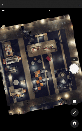
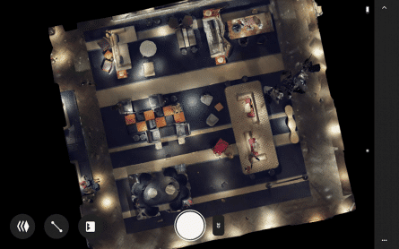
Capture for Android works as flexibly and simply as on iOS, making it a cinch to connect a Matterport Pro2 or six of the most popular 360 cameras made by our partners, Insta360 and Ricoh. So if you or your company already uses the Matterport platform, the free app can be downloaded onto the compatible Android devices you already own, making it fast and easy to mobilize more people on your team to capture spaces.
If you don’t own a compatible camera, check out the options below. The Matterport Pro2 is the right pick if you are scanning a large volume of spaces and high accuracy and image quality are important to you. If portability and affordability are key factors, then choose a 360 camera. They are a great choice for scanning small to medium size spaces. You can compare cameras here.
Check out this video to see how easy it is to get started. And then download the free Matterport Capture app on Google Play today. We’re excited to know what you think.
Learn more
Below is more information on Matterport Capture for Android. Note that additional information on requirements and support can also be found on our support page:
Minimum Requirements for Supported Android Devices
- Android OS – 8.X (Oreo), 9.X (Pie) , 10.X (Q), 11.X
- 3 GB of RAM or more
- Android devices certified by Google and unrooted.
- Modern devices with a 64-bit architecture
Supported Cameras
- Matterport Pro2 3D camera
- Matterport Pro2 Lite 3D camera
- Matterport Pro 3D Camera
- Insta360 ONE X
- Insta360 ONE R
- Insta360 ONE X2
- Ricoh Theta Z1
- Ricoh Theta V
- Ricoh Theta SC2
Supported languages
12 languages including, English, French, German, Spanish, Italian, Dutch, Russian, Brazilian Portuguese, Japanese, Korean, Chinese (Simplified), Chinese (Traditional).
We’ll keep on building and adding to this list, and please stay tuned for updates on Matterport for Android, giving you the ability to capture 3D spaces using just the camera on your Android device