Civil 3D: Sharing Assemblies
So, you’re the technical team lead for your Civil Engineering firm, and you need to share amongst your team some Civil 3D Assemblies.
You know how to create an AutoCAD tool palette, and you know that this is the best place to share assemblies – but you’ve tried, and it’s not working.
If you’d like to learn how this is done read on.
Palettes can be exported and then imported onto users’ machines, but when an assembly is edited, the creator must export again and then all the users must again import. This is not efficient.
The Hard Way
The method that Civil 3D uses to store assemblies on a palette works well, but to set it up is a bit of a bear. Open this document to see the full details. Here is a summary:
- When an assembly is dragged to a tool palette a new DWG is created on your system. For my system this is:
C:\ProgramData\Autodesk\C3D 2022\enu\Assemblies\Metric - You can create a tool palette with custom assemblies, sure, but you need to make these drawings available to your users. Usually, this means copying them to a network shared folder.
- Even when you make them available, the DWG path must be defined in an ATC file that defines the palette, This is XML programming language and it can be difficult to find and disastrous if an error is made.
The Easy Way
I won’t say this is “The Best” method, but I believe it to be the easiest, quickest, and most foolproof method; and it’s the one I choose to use at this time.
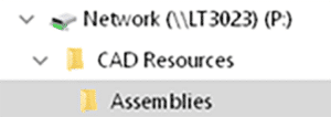
I won’t go into detail about how to perform each of these steps; it is assumed you know the technique. The short answer is that each assembly will reside in its own DWG file and that file will be stored in the shared network folder. That file will be a block in the tool palette.
Open a drawing that conforms to your Civil 3D standards. Possibly one that already contains your desired assembly.
- If the assembly has yet to be created, create it.
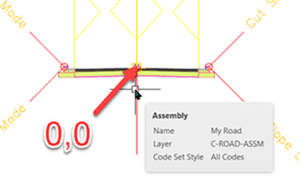
- Ensure it is on the desired layer. Assign the desired code set style to it. Move it from its insertion point to 0,0. If this last step is skipped, the assembly will not be inserted properly later.
3. Save the drawing to your shared network folder.
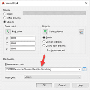
4. WBLOCK and select the assembly and subassemblies together. Ensure the insertion coordinates are 0,0,0 and provide the file name. Click OK to create the drawing.
5. Create a new tool palette or set current the destination palette for your new assemblies. Drag the newly created drawing into the palette.
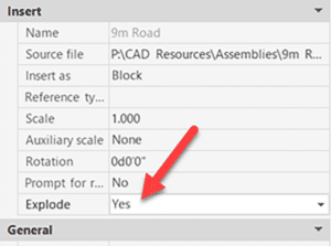
6. To use the new assembly, drag it from the palette into a new drawing. This will be a block, however. It will need to be exploded once.

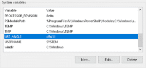
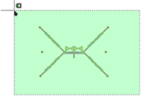
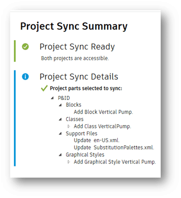
7. You may suggest turning on the Explode option in the tool to avoid the explode step. Indeed, I thought of that as well. Problem is, this is what you get!
That’s it. Once the assemblies have been created, it takes about 45 seconds per assembly to add to the palette. If edits are required, simply open the appropriate DWG, make the edits, and save.


_hr")