The CTC BIM Project Suite is geared towards users doing the project work, the included tools aim to make everyday project work easier and more efficient that using Revit tools alone. There are 5 free tools accessed from the ribbon while working in Revit, as well as Revit Properties which is access from the File Explorer to allow you access to Revit file properties, such as the Revit version. The paid version of the Project Suite has an additional 13 tools to add to the Revit workflow. The 2022 release of CTC BIM Project Suite saw the addition of a new free tool, View Aligner.
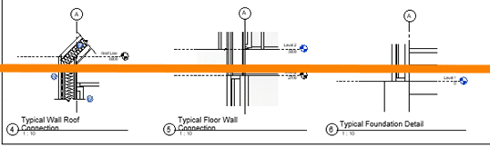
This tool allows you to select any view on a sheet and align the other views to it based on your project needs. The greatest advantage to the View Aligner tool is that it works across sheets.
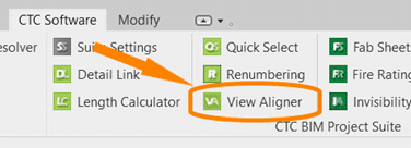
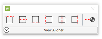
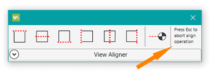
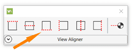
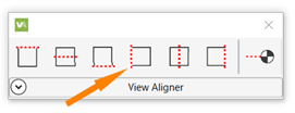
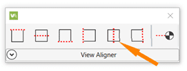
When selected from the tools on the ribbon the floating tool bar appears and can be repositioned to a convenient location.
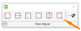
You have the option of 7 alignments, based on the crop boundary of the views. You can align by each edge; top, bottom, left or right, by either horizontal or vertical centerlines, or by levels.
Upon selection of the desired alignment, instructions for ending the operation appear at the end of the toolbar.
If you click back on the toolbar before pressing Esc you will need to click back into the view (so the toolbar goes white again) before you can press Esc to exit.
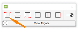
Align Horizontally by Top Edge
Select the Align Horizontally by Top Edge icon.
Select the view with the position you want to align to.
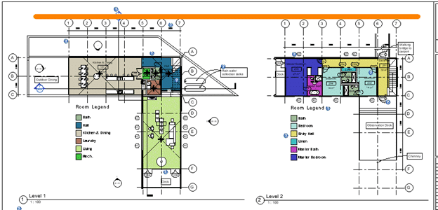
Every view you click will now align horizontally top edge to top edge of the crop region.
Press Esc to complete the operation.
To keep crop regions the same size for all plan views, use a scope box to control the edges.
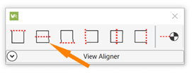
Align Horizontally by Centerline
Select the Align Horizontally by Centerline icon.
Select the view with the position you want to align to.
Every view you click will now align horizontally centerline to centerline of the crop region.
Press Esc to complete the operation.
For details that don’t show the crop region try using centerlines to get the massing relatively aligned then adjust view names for a nice symmetrical look.
Align Horizontally by Bottom Edge
Select the Align Horizontally by Bottom Edge icon.
Select the view with the position you want to align to.
Every view you click will now align horizontally bottom edge to bottom edge of the crop region.
Press Esc to complete the operation.
Align the bottom of images to help determine the spacing for other elements on the sheet.
Align Vertically by Left Edge
Select the Align Vertically by Left Edge icon.
Select the view with the position you want to align to.
Every view you click will now align Vertically left edge to left edge of the crop region.
Press Esc to complete the operation.
Align images along the edge of a page for a nice crisp line.
Align Vertically by Centerline
Select the Align Vertically by Centerline icon.
Select the view with the position you want to align to.
Every view you click will now align vertically centerline to centerline of the crop region.
Press Esc to complete the operation.
Vertical alignment by centerline works best with the unrelated views that Revit can’t snap alignment to.
Align Vertically by Right Edge
Select the Align Vertically by Right Edge icon.
Select the view with the position you want to align to.
Every view you click will now align Vertically right edge to right edge of the crop region.
Press Esc to complete the operation.
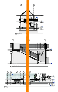
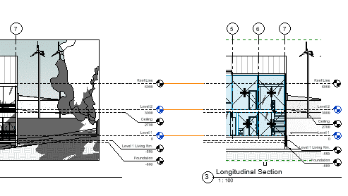
Using a right edge alignment (or left) for elevations results in a cohesive look when grid bulbs for all views are aligned to the same side.
Align By Levels
Select the Align by Levels icon.
Select the view with the position you want to align to.
Every view you click will now align by levels.
Press Esc to complete the operation.
To use this alignment the scale of the views must be the same.
TIPS:
Use the View Alignment tool to align ‘like’ items.
Assign a scope box to the crop regions to make alignment quicker.
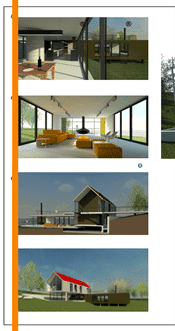
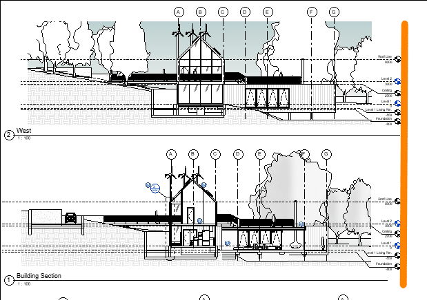
Open each sheet you will be working on before starting the tool to use alignment across the sheets. You cannot access the project browser once the tool is active. Use the view tabs to flip between sheets to align the views horizontal across each sheet, then do the same to align vertically.
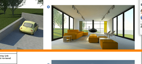
Alignment works best on views of the same type. As seen below when you align an image and a schedule the space between visible content and the outermost edge of the crop boundary are not the same so despite being aligned the appear “off”.
Get your 2022 release of CTC BIM Project Suite and try the FREE View Aligner tool on your next project. Reach out to us at info@solidcad.ca
Digital transformation is essential for any business looking to navigate the post-COVID world that exists today. Before the pandemic, the focus on digital transformation was high but has increased due to a large portion of the labor force relying on easily accessible data at home.
At the heart of any successful digital transformation project is accurate data structure.
What Is Digital Transformation?
Digital transformation refers to the process of shifting operations, data, and tools commonly available in offline or non-interactive environments to a completely digital solution. Digital transformation can yield the following benefits:
Increased visibility to data trends will lead to an improved understanding of the customer experience and an uplift in sales
Provide reports that highlight improvement opportunities within common workflows that reduce costs and increase efficiency
While the benefits of digital transformation have been on display for many years, some businesses view this practice as a lower priority. Specifically, asset-heavy organizations are reluctant to change and move their information online or revamp their technical infrastructure. Instead, these businesses prefer to continue maintaining older and outdated systems to minimize the impact on existing day-to-day operations.
How COVID-19 has Pushed Digital Transformation to the Forefront
With the onset of the pandemic, organizations have needed to scramble to enable remote operations, social distancing, and continue to maintain assets across multiple sites and locations. Suddenly digital transformation is now a requirement for many businesses.
This has been a difficult transition period for organizations that didn’t have an existing plan in place. Effective data structure has emerged as an essential piece of this transformation.
Digital Transformation is Built on Strong Data Structure
Well governed and structured data is the basis of a well-executed digital transformation. The amount of data can be overwhelming for asset-heavy organizations and found in different sources such as:
Work orders
Asset data and maintenance records
Data coming in from various other mission-critical tools – i.e., EDMS or CMMS solutions
MRO inventory data
Pen and paper documentation
Unstructured Data Can Lead to Long Drawn-out Digital Transformation
Most organizations have their data spread over different locations and tools. This data can also be inaccessible by various teams and generally unstructured. Here are a few reasons why:
Knowledge is often spread by word-of-mouth with no documentation available
Data consists of a combination of paper, on-premise, and cloud-based tools. This inconsistency leads to incomplete information, poor document version control, and more
Existing digital solutions work independently of each other with little integration
Day-to-day digital workflows are not standardized or governed for good data structure
Incomplete Data Leads To Poor Asset Structure
If your asset-intensive organization has poor data quality, this will affect your asset structure. All the information surrounding an asset (i.e., documentation, compliance, maintenance plans, etc.) will be affected by default, which can lead to:
Incomplete data sets
Out-of-date information
Trouble maintaining industry compliance
Higher costs to maintain data infrastructure
Data security issues
Increased risk of a digital transformation project failing
Once a weak data structure exists, the related issues will carry over into other complementary solutions. The lack of robust and available data will affect other data-driven automation and Industrial Internet of Things (IIoT) projects. These solutions require a complete and comprehensive data structure to build and implement successfully.
How to Ensure your Data and Asset Structure is Correct
To set up your business for a successful Digital Transformation, you can improve your data structure by focusing on accurate data, robust data structure, and data governance.
1. Review Your Current Data
Reviewing your current data should be the first step for improving the existing data structure. This requires that you answer vital questions about your data itself, including:
What data do you have?
What information are you collecting regularly?
How and where is the data used?
What does that data tell you about your customers, about your KPIs, about your business?
Identify missing data opportunities. Where are there currently gaps in your data needs?
Leading off with a review of current data will help your team understand your data and what you do with it.
2. Organize your Data with the Appropriate Tools
The next step is to use a well-structured tool to import your data. Using a tool that can assist with proper data structure, governance, and analytical insights will ease your path to digital transformation by:
Providing automation of workflows to increase data entry efficiency and ensure data accuracy by avoiding human error
Confirming your data initiatives are standardized and repeatable
Guarantee that your organization can easily manage your information’s flow, quality, and governance, which is key to any compelling insights or transformation efforts
Selecting the right solution will vary by your organization’s industry, data sources, and required integrations. The right tool will provide a broader view and understanding of your data as a whole to your entire team.
What Types of Tools fit best For Asset-Intensive Organizations?
Most successfulasset-heavy organizations already use a CMMS or EAM solution for their maintenance tracking needs. It allows you to digitize and automate maintenance operations to deploy preventive maintenance strategies better, develop better maintenance practices, stay organized, and ultimately save time and money. While this is a significant first step into modernizing your digital data footprint, a CMMS system alone is missing essential functionality for maintaining your data structure in other areas (i.e., technical drawings and documentation). This functionality is where an EDMS solution excels.
Pairing an EDMS with a CMMS solution is the winning combination that empowers your team with the following benefits:
A fully connected digital single source of truth with high availability
Automation across multiple tools to improve efficiency and data accuracy
Easy to manage data governance over the entire technological stack
In a post-COVID world, organizations that complete digital transformations and modernize their operations will pull past competitors relying on legacy systems. But making the transition begins with reliable data and solid asset structure as a first step.
To learn more about Meridian solutions (EDMS and CMMS) and how they can help your team, don’t hesitate to get in touch with the SolidCAD Meridian team.
In this vlog, our Civil/Infrastructure Technical Product Specialist, Jae Kwon, will demonstrate how to assign point layers by Note Column with Dynamo application.
Autodesk Dynamo is a programming environment that requires no programming experience. Dynamo enables designers to create visual logic so they can explore a wide range of parametric conceptual designs using logic, simple data and analysis without the need to create a physical prototype.
We are excited to announce that our partner CTC Software released Civil 3D CIM Project and Manager Suites, version 22.0.1. It is now released and can be accessed on the CTC website.
This update saw a lot of fixes and enhancements to new products released in 22.0.0 and before.
Below are release notes:
22.0.1
8/17/2021
CIM Project Suite
Pipe Planner
Bug Fix
Fixed a variety of issues causing Pipe Planner to error out or crash. Improved application speed performance. Fixed issues with exporting to external spreadsheets. Fixed issues with importing external spreadsheets.
22.0.1
8/17/2021
CIM Project Suite
Pipe Planner
Enhancement
Added support for formulas in user-defined empty columns and rows. Added properties filter search bar. Added interactive selection of export starting cell. Improved part renaming, allowing old names to be reused on new part names within the same operation. Added new right-click options to edit the middle table. Misc. enhancements and performance improvements.
22.0.1
8/17/2021
CIM Project Suite
Pipe Designer
Enhancement
Improved part renaming, allowing old names to be reused on new part names within the same operation.
22.0.1
8/17/2021
CIM Project Suite
Label Genie
Enhancement
Added option to manually select anchor objects in drawings. Added option when labeling layouts to create a unique layer for each layout.
22.0.1
8/17/2021
CIM Project Suite
Label Genie
Bug Fix
Fixed an issue where layout-specific labeling was not respecting exact viewport extents. Fixed an issue where segment labels were not following the assigned layer. Fixed misc. issues with specific drawing files.
22.0.1
8/17/2021
CIM Project Suite
Earthwork Processer
Bug Fix
Fixed an issue where errors occurred if existing or proposed surfaces were empty or not overlapping one another. Fixed an issue where earthwork region polylines that were significantly small would not offset and cause the app to error.
22.0.1
8/17/2021
CIM Project Suite
Data Wizard
Bug Fix
Fixed an issue where survey figures caused Data Wizard to error.
22.0.1
8/17/2021
CIM Project Suite
Parts Swapper
Bug Fix
Fixed an issue where parts not found in the parts catalog were causing Parts Swapper to file.
22.0.1
8/17/2021
CIM Project Suite
Corridor Mapper
Bug Fix
Fixed an issue where changes to assemblies would cause the app to error.
22.0.1
8/17/2021
CIM Project Suite
CIM Project Suite
Bug Fix
Fixed an issue where custom subassemblies were breaking when CIM Project Suite was installed.
22.0.1
8/17/2021
CIM Manager Suite
Template Tracker
Bug Fix
Fixed an issue where pressure network band styles were causing Template Tracker to error out.
22.0.1
8/17/2021
CIM Manager Suite
CIM Manager Suite
Bug Fix
Fixed an issue where custom subassemblies were breaking when CIM Manager Suite was installed.
Whelan Construction is a general contracting and construction management organization that specializes in end-to-end construction services. They serve Metro Vancouver, Fraser Valley, and Squamish-Lillooet regions and specialize in Institutional, Healthcare, Light Rail, Airport, Renewable Energy and Building Performance Upgrade projects in the region of $1,000,000 to $25,000,000.
Based in Vancouver, B.C., Whelan Construction has Irish roots. Founder, Brian Whelan, emigrated to Canada in 2013 and—from one west coast to another. Brian has successfully led the construction of $400,000,000 worth of projects including airport, healthcare, residential, institutional, marine, pharmaceutical, light industrial, retail, and commercial projects.
How Autodesk Construction Cloud has helped start-up Whelan Construction win bids over competitors
The Challenge
As a start-up company, Whelan Construction faced challenges in identifying the right solutions and systems that would ensure a smooth and consistent workflow process to deliver end-to-end construction services for all stages of a project.
Outside of the solution requirements, one of the biggest challenges that Whelan Construction’s founder, Brian Whelan had experienced, was selecting a suitable project and field management software package for a small to medium sized construction company, a package that seamlessly connects the field and office.
The Solution
Given Autodesk’s extensive product portfolio, SolidCAD helped Whelan Construction to determine the right software solutions that goes together with their needs and the construction industry’s best practices requirements.
With Autodesk Construction Cloud, specifically, Autodesk Docs, Build, AutoCAD, and PDF solution Bluebeam, Whelan Construction now has a common environment for all project-related data all while helping to manage projects with minimal resources and complete project entries in one platform.
Bluebeam allowed project partners to be able to mark up and collaborate on the same documents in real-time. While, Autodesk Docs + Build, one of the industry’s leading solutions made it easy for Whelan Construction’s team to work with other project stakeholders, have connected workflows, increased transparency, and track construction progress throughout the entire lifecycle of their projects.
Moreover, Whelan Construction took one-on-one training with SolidCAD on the Docs + Cost Management component of the Autodesk Build to connect project management and field execution data to cost activities to understand root causes and scope cost impacts.
The Outcome
Whelan Construction is now able to ensure projects stay on track; improve collaboration and reduce miscommunication, potential errors, and rework. With the ability to track all issues in one place and reduce costly rework, Whelan Construction can now keep projects on schedule all while being able to manage project data and project bids.
Aside from that, they can now develop very detailed proposals with an ability to give the preview on designs and project development stages as required, providing them a competitive edge when winning bids.
As a result, Whelan Construction was able to apply the skills obtained from training to compile professional and successful bids.
SolidCAD continues to be a resource in helping Whelan Construction grow as a construction company in this competitive market.
Testimonial
SolidCAD has been fantastic in providing my new company with support for Autodesk Docs and Build, Bluebeam, and AutoCAD. Ian was great to deal with when organizing the right package and considering the most economical plan for a small start-up construction company. Andrew went above and beyond and provided classroom sessions for Autodesk Docs and Build. He has been brilliant and treated our company like partners, so much so that I now have three licenses on the books. I started using AutoCAD R14 a long time ago and have always trusted Autodesk products. This was one of the reasons I chose Autodesk Docs and Build, one for reputation, and two the turnkey management services that the product does is fantastic.
I would highly recommend using the SolidCAD team.
-Brian Whelan, Construction Manager at the Whelan Construction
Paper Excellence is a diversified manufacturer of pulp and paper, including printing and writing, packaging, and specialty papers. We believe in the enduring value of wood-based products in global markets and have built a large…
Quinn Digital Asset Protection Inc. Customer Success Story
Quinn Digital Asset Protection Inc. has been in the business of protecting property, product, and people assets since 2006, but our team of over 30 professionals has many decades of experience in the asset protection…
Starline Windows is an industry leader in the design and manufacturing of architectural aluminum window systems, as well as residential vinyl windows and doors for over 50 years. They have completed thousands of contracts and…
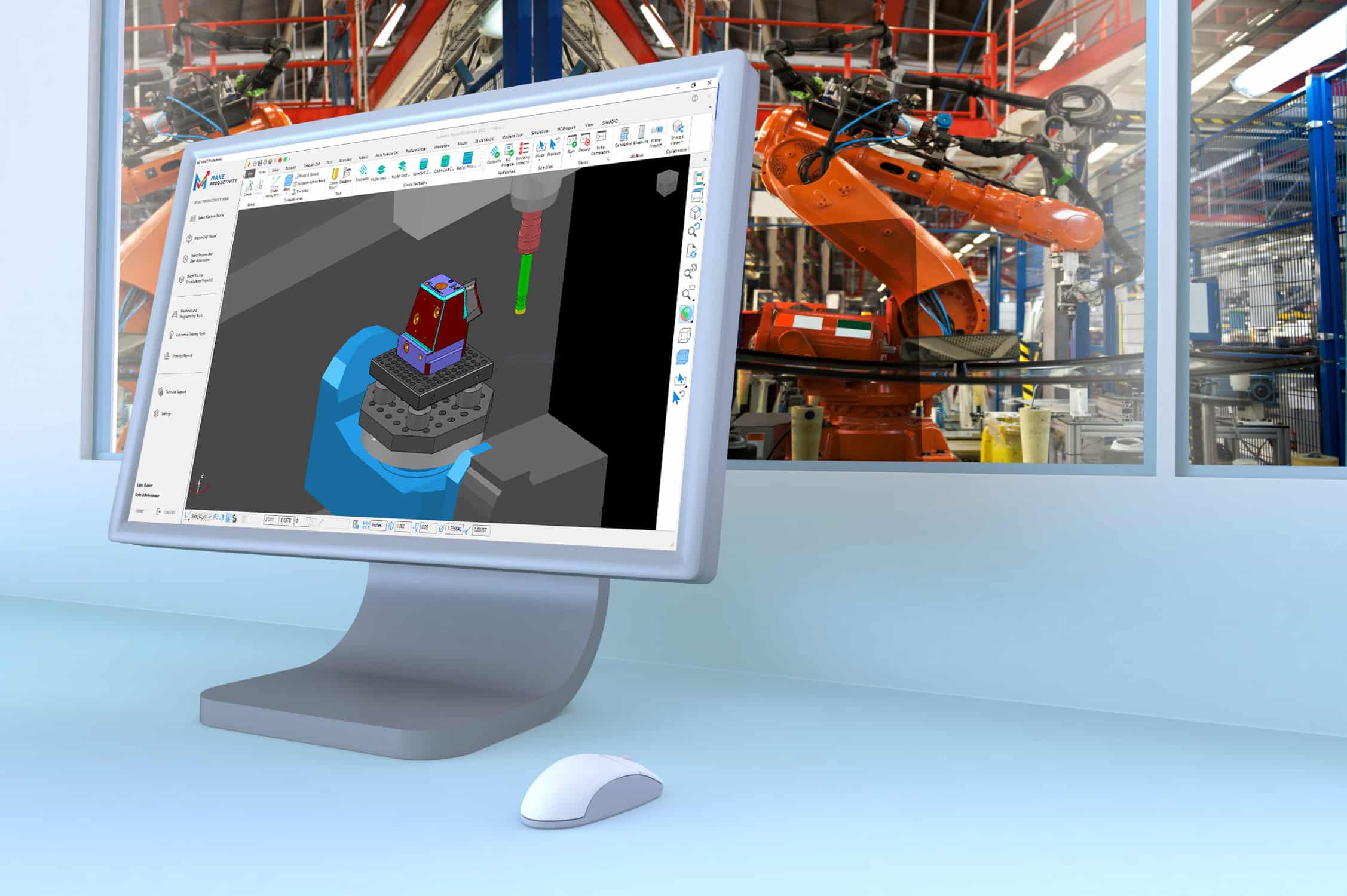
TORONTO, ON August 23, 2021 – Today, SolidCAD, Canada’s largest professional services company and Autodesk Platinum Partner, announces the launch of their newest product, MAKE Productivity. MAKE Productivity for PowerMill® is a best-in-class tool to boost CAM programming productivity, provide incredible staffing flexibility to overcome skilled labour shortages, and optimize machine scheduling and utilization by programming well ahead of run-time.
Equipped with a suite of calculators and tools for daily programming, MAKE Productivity provides endless capabilities for automating simple and complex multi-axis manufacturing processes, along with “on-demand” digital learning modules and training content for the user’s self-directed learning plans.
MAKE Productivity can allow users to automate 90-100% of their complex finish programming by using the guided workflow. Paired with Autodesk’s PowerMill® Ultimate, this product allows for simultaneous 5-axis programming automation and enhanced machine simulation of NC programs, tool changes, and laser cycles. Users can now optimize after-hours license use by creating a batch calculation queue for “lights-out” calculation of multiple projects.
“SolidCAD is responding to our customer’s needs for a robust and customizable solution to automate their complex CAM programming processes.” says Robert Kobielski, Sales Manager of Advanced Manufacturing at SolidCAD. “MAKE Productivity is providing the enhancements and value-added tools for which our customers have been requesting, and we are pleased to have developed this collaboratively to suit these needs.”
SolidCAD offers two versions of the product that work with Autodesk’s Standard or Ultimate versions of PowerMill®. With MAKE Productivity and PowerMill® Standard, users will have the ability to rapidly create NC code for high-speed 3-axis machining, 3+2 programming, 2.5D milling, turning, and toolpath safety verification. While MAKE Productivity and PowerMill® Ultimate will have all the standard features plus machine simulation, tool change and laser cycle validation, and access to full 5-axis programming with automatic collision avoidance, robot programming, electrode programming, hybrid manufacturing, and more.
SolidCAD will also be attending this year’s Canadian Manufacturing Technology Show (CMTS) from October 4-7, 2021, in Toronto at the International Centre. Stop by to get a first look in-person of MAKE productivity at Booth #2631.
In my opinion, the most painful product lifecycle management (PLM) failures happen when companies struggle to understand the concept and implement it in their organization. This technology is made to help them. When I speak to companies, I hear things like – “We tried to organize ourselves, but PLM was such a complex idea. We decided to stay unorganized.” It hurts me to think about the failures of technology despite the powerful idea of PLM.
I want to focus on explaining why you need PLM and how to identify if it can help support your product development and manufacturing operations. Understanding this will help you get prepared and organized for the digital future.
CIMdata defined digitalization as “The business strategy best geared to extract real-world value from digital data”, whereas their definition of PLM refers to a “strategic business approach, NOT just technologies, a consistent set of business solutions”.
I’ve noticed a growing interest in product lifecycle management and its benefits in the last year. As companies look to improve their product offerings, refine supply chains, and organize their business, PLM is one of the best tools to achieve these goals.
When implementing PLM, your organization should be setting goals and KPIs regularily along the way. Our software will allow you to collaborate with SolidCAD and suppliers to integrate important data from their end as you assess each step in your process.
As your organization goes through each of these stages, you should be collecting and entering data into your PLM software. We will help you streamline the process and allow you to eliminate tedious data re-entry. This means that your PLM software should smoothly integrate with your enterprise resource planning (ERP) system.
You may be wondering why PLM is important for our digital future. Expected results for companies using PLM software include:
Lower product costs:
PLM is an iterative process that your organization will refine with each cycle, one of the most common goals is to lower production costs. This may seem intuitive for any company that engages in product development, but it’s important to point out that PLM achieves this by creating a more refined supply chain along with a streamlined production process.
Greater product quality:
In a similar artery to lowering product costs, product quality should increase as you foster the PLM process. Whether it’s finding more diverse materials or better parts at the right price, each cycle should push you to assess your sourcing, development, and production methods to improve your offerings.
Faster time to market:
This is a direct result of improving your supply chain along with manufacturing and logistics. PLM is not only a about single product throughout its lifecycle; it is a tool to have comparable data that allows you to streamline and improve the steps in your process.
So, what does PLM currently offer? PLM provides a central repository of accurate information that geographically dispersed personnel can access. In a post-2020 world where more and more teams are working remotely, there’s undeniable value in this system that facilitates accurate data sharing and collaboration don’t you think?
To summarize, here are the 5 main reasons that you will need PLM based on my knowledge and conversations with customers:
Increased productivity: PLM facilitates the process of lifecycle management and drives improvements across the series of cycles for the given product. Implementing a scalable PLM platform increases employee productivity by consolidating designs, communications, workflows, and product data in a single place.
Accelerated time to market: The smoother the workflow and the higher the productivity, the faster your organization will be able to bring products to market.
Increased revenue: As you accelerate your time to market with PLM, you’ll also be reducing production costs. The intersection between those two actions will improve your margin and help you scale up your business. You can’t just think of PLM as a way of improving workflows; one of the most critical KPIs after a few cycles is how it is impacting your revenue.
Accurate data sharing: PLM organizes your data, helps you keep track of it, and allows for sharing with the right stakeholders at the right time (both internal and external).
Improved product quality: More accurate data and improved workflows are always going to lead to improved product quality. I believe, that is another contributing factor to increased revenue. Regardless of an organization’s position in the supply chain. That stands for both business and commercial transactions. As you refine your PLM steps and drive even minor improvements, you’ll see the difference in the product for sure!
From a business development representatives’ point of view to you, I can assure you that lifecycle management issues can be found across small, medium, and large business. When it comes to growing and improving your company, PLM solutions are the digital future.
PG Design Studio specializes in delivering projects using a collaborative Integrated Project Delivery approach. They pride themselves on working closely with clients, developers, stakeholders, builders, sub-trades, procurement specialists and project consultants through all stages of the project, delivering well-coordinated, efficient building designs.
PG Design Studio strives to deliver strong project concepts, innovative ideas, and strategies that fit the specific requirements of each site, client, and program. They focus on addressing human, urban, geographical, environmental, functional, and practical considerations, with a unique architectural style, resulting in the construction of many award-winning projects.
Project Profile
Challenge
PG Design Studio is unique because they are often the developer, architect, and construction company all in one. With a wide range of services and diverse internal teams, they require seamless collaboration between different departments and various software solutions. PG Design Studio was looking for a platform that can be easily integrated into their existing workflow, easily share project related data, and provide them an all-inclusive portfolio of products that would help them from design to construction.
In addition, with such a large team, that works both remotely and on-site, they were experiencing challenges on finding a product with the right type of cloud-based features. They required a cloud-based solution that would let their teams access project data from multiple devices and locations at anytime.
Solution
PG Design turned to SolidCAD to purchase and implement Autodesk Construction Cloud (ACC) into their existing workflow. The ACC solution provided them a common data environment for all project-related information, connected their workflows, and therefore helped them meet their need for an all-inclusive product. The project data was also stored on PG Design’s other enterprise technology solutions such as Microsoft and Autodesk AEC Collection more specifically, Revit, which was successfully integrated with the ACC solution.
The nature of the cloud-based platform also gave them the ability of easy, flexible access from multiple devices for everyone involved in the project.
Outside of SolidCAD helping them with the implementation of ACC products, SolidCAD continues to provide ongoing training and implementation support and has been a special resource to many of their projects. Particularly, SolidCAD has built a tool to help PG Design mass import 10 years of old projects from their local services to BIM 360 to ensure their data is now in one central location.
Results
In the end, PG Design Studio, was able to streamline their technology spend with the integration of Autodesk and Microsoft. Project teams both internal and external now have access to all key project data in a single location. With the centralization of this information, they can deliver higher quality in less time with reduced risk on all projects. That was also positive reflected in their project KPIs when it came down to reducing risk, maximizing efficiency, and increasing profits.
PG Design Studio chose SolidCAD due to their strong and long-lasting relationship with the company. Over the last 8 years they have been confident that whenever they required software, support, or training, SolidCAD was there to help and cater to all their unique needs.
Testimonial
“In today’s AEC industry, many of us are always looking for ways to be more efficient. The SolidCAD team is support we can rely on, especially when it comes to achieving our goals. Thanks to SolidCAD, our ability to make new technologies a norm allows us to stay ahead of the game. Autodesk Construction Cloud helps us connect our project teams and data in real-time, from the design phase through construction, supporting informed decision-making and leading to more predictable and profitable outcomes.“
SolidCAD Development scope and built a tool to mass import 10 years of old project from their local service to BIM 360 (this included the project setup and files)
Similar Projects
Transforming Learning and Efficiency at NORR: Growth with Pinnacle Series
Discover how NORR enhanced team performance and training with Pinnacle Series and SolidCAD’s support—unlocking smarter onboarding, improved software adoption, and a stronger learning culture across the organization.[...]
Équipe Laurence: Driving Growth and Efficiency with BIM
Discover how Équipe Laurence transformed its civil engineering operations with BIM and SolidCAD’s support, achieving greater efficiency, precision, and project scalability.[...]
Ian Robertson Design Elevates Client Engagement with BIM
Ian Robertson Design, renowned for luxury residential projects, partnered with SolidCAD to fully implement Building Information Modeling (BIM), enhancing client engagement through advanced visualization tools and streamlined workflows. [...]
ne powerful feature in Bluebeam Revu I think everyone should be using in some capacity is Layers.
If you come to Revu with a CAD background, you probably understand and use Layers already. For those who don’t, you just don’t know what you don’t know. I hope this article helps shed light on a new opportunity to add flexibility, organization and clarity to your PDF workflows.
For those old enough, Layers could be described like this: Remember in grade school when the teacher used the overhead projector to show things on the wall or pull-down screen? The surface of the overhead is the PDF when you open it. The clear film they write and draw on is a layer. That layer can be taken off or hidden, turned back on, or you could overlay several different layers to see them all on the screen.
In Revu, we can isolate categories of markups or flatten them. If you’re not familiar with the Flatten function, refer back to this previous blog post.
You might be asking: “Where do we find Layers?” There are a few places.
First, let’s look at the Panels on the sides of the Revu interface. You should see a black vertical bar on the side with several panel tabs toward the top. Right-click below the tools and hover over “Show.”
There, you’ll then see a list of Panels; click on the Layers option. When it turns blue, that means it’s visible.
Another place you will see Layers is, when you open a document printed from drafting/design tools, they will often transfer from the original file. To quickly see what Layers look like and how they can be powerful, try the Overlay Pages tool. If you’re not already using Overlay Pages when revisions cross your desk, brace yourself.
Here are some quick definitions of how Layers could be used for different phases of the project lifecycle.
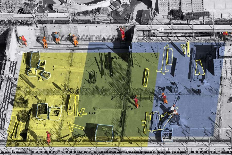
Planning: When planning a new construction development, you might use Layers to break down different elements of design requirements. For example, you might have individual Layers for building area, parking, green space, etc.
Design Review: During the design and review phase, you might have Layers and colors indicating markups needing to be added to the drawings, markups which are just comments to the drafter for reference or internal notes for design intent. You might even have Layers to track first-round markups and another for additional comments after the backcheck.
Estimating: When I build custom tools for estimating, I like to always include Layers to break down systems or material types. I always reverse engineer the tools and think about how I might manipulate the Layers when the sheet is full of markups. You might want to turn off all the flooring area measurements so you can see all the transition strips.
Hiding all the concrete slabs will make it easier to see and select the isolated footing, or maybe you only want to see the continuous strip footings. Layers allow you to isolate materials so you can build out the estimate without having all material Layers on at the same time.
Site Preparation: On the civil design side, you might want to get quantities and differentiate cut-and-fill areas indicating what materials can be reused someplace else on site. If you’re recording progress with site images or survey points, you might organize those by date as well.
Construction: During construction, we can use Layers to break down your schedule. Looking at the estimating markups, you could determine how many concrete trucks come each day and isolate the curbs, slabs and footing accordingly. You could also use it for site logistics locating material deliveries, job trailers and portable toilets on site with a date layer. Knowing what needs to move on site as the project progresses can keep everyone informed on expectations.
As-Builts: When on site recording existing conditions, P&ID or verifying installation, Layers can be used to indicate new vs. existing, supply vs. return, gas vs. water piping or to indicate valves that need to be replaced.
Facility Management: When tracking so many systems in a facility, it can help to keep them all in one drawing and use Layers to organize them. When all the Layers are on, it might seem like an organized mess, but when you isolate the low voltage layer to investigate a network problem, suddenly it’s clean and precise. After you solve that emergency, you might switch Layers for a plumbing issue or verify the dates on fire extinguishers.
Extra Credit: Incorporate Layers so those markups you do early in a project are still used downstream, eliminating redundant work. I’ve worked with several specialty contractors building tools for the sales team to layout while walking a site with the owner. All the devices are built with pricing, so they immediately have an estimate.
Those same markups are moved and revised by the engineering team back in the office, with the estimate being updated automatically. When revisions pass through, they have direct visuals of scope creep and price increases. These markups can also be used by the installation team on site, changing the status of each device as they complete the install. In Studio Sessions in Revu, the project manager knows in real time how much work remains on site, helping him schedule the next project.
As you can see, there are many powerful ways to use Layers throughout all phases of a construction project. I hope you found this introduction to Layers in Revu helpful and you have some new ideas of how you might implement them into your workflows.


")
")