• Canadian Flag Proudly Canadian Owned and Operated
  • How to Use Revu to Create Successful Bids

    This story was originally published by  on the Bluebeam Blog.

    With smart PDFs now being generated as part of bid packages thanks to a variety of digital tools within the marketplace, end–users can now use technology to boost the visual appeal, accuracy, and overall value of bid packages.
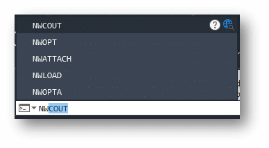
    Bluebeam Revu can actually make use of those smart PDFs by making sure that it allows estimators to take off quantities accurately,” said Deepak Maini, a qualified mechanical engineer with two decades of experience. “The tools that you’ve got available in Bluebeam Revu, the accuracy of picking regions, the accuracy of visually searching items, and the standardization potential make it a great asset to making a successful bid package.”

    Three keys to a successful bid

    • Accuracy of the scale of the sheet
    • The right set of customizable and standardized digital tools
    • Accurate cost values associated with materials and labor

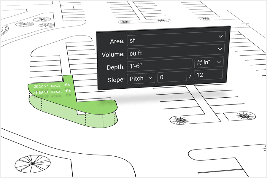
    Quantity takeoffs and accuracy

    Now a noted guest lecturer at the University of Technology Sydney (UTS) and University of New South Wales (UNSW), Maini, the current national technical manager for Cadgroup Australia, advocates for paperless bid packages and credits Revu as a crucial piece of the puzzle.

    “In the Australia-New Zealand market, and actually in the global market as a whole, the climate is very competitive,” Maini said. “The process of taking off quantities within today’s market needs to be accurate and needs to be fast. And that’s where Bluebeam Revu plays a massive role. With it, the estimator can take off quantities on one job and then quickly get onto the next job without wasting too much time.”

    “There’s absolutely no comparison between Revu and paper,” Maini continued. “We are talking about projects going in hundreds of millions of dollars and billions of dollars as well, which means that you’ve got these PDF sheets getting delivered to you, which are not two or three sheets. You’ve got 100-150 sheets getting delivered and that’s why taking off quantities using an accurate process is really important.”

    Digital collaboration with Bluebeam

    Ensuring scale can also be achieved within the sophisticated calibration capabilities in Revu. This is crucial when receiving documents as you don’t have to rely on the imagery to be accurate in scale, which could be a huge issue for estimation.

    “In Revu, we calibrate the sheet and we find out what scale the objects are at, and then when we are taking off the quantities, it ensures that we use the right scale and we get the right measurements,” Deepak said.

    Standardizing

    Being able to consistently takeoff accurate quantities is essential to completing bid packages in a timely and accurate manner.

    “This is again where Bluebeam Revu is absolutely fantastic,” Maini said. “I create certain specialized and takeoff tools, I can then have them sitting in my own custom toolset, and then I can distribute the toolset within my own team, which means that everybody who’s taking off the quantities will have the same display of quantities. ”

    Cost values can also be plugged into Revu, allowing instant dollar projections for the project. “As you take off the quantities, it gives you the dollar value of that quantity right there in front of you,” Maini said. “You can have that displayed as a table on the sheet, which means that you can straight away find out how much it’s going to cost you.”

    The ability within the digital tools in Revu to drive accuracy and consistency among estimators allows firms the flexibility to more accurately staff projects, without the risk of lesser experienced estimators using a process of their own, which might hinder the accuracy of the quantity takeoffs and the success of the bid as a whole.

    Mega Mold International Inc.

    Success Stories

    Mega Mold International Inc.

    Mega Mold produces the best world class tooling for the automotive, industrial and consumer markets.  For over 28 years, their team of specialists deliver tooling that is superior in class for cycle time and part quality in all aspects of plastic injection mold designs.

    Mega Mold provides their customers quality services including:

    • Standard Injection
    • Multi-shot Rotary
    • Stack Molds
    • Aluminum Production Tools
    • Compression Tools
    • Proto-type Tooling
    • Gas Assist
    • Insert Molding

    Mega Mold and members of the SolidCAD team have had a long-lasting partnership that predates SolidCAD and began over 20 years ago.  As a loyal and legacy customer, SolidCAD’s advanced manufacturing team has always provided the knowledge and assistance throughout Mega Mold’s growth.

    Improving efficiency with Fusion 360 Probing

    The Challenge

    As a leader in the tooling industry, Mega Mold needed an advanced solution with powerful capabilities that could check features during the machining process, automate tedious tasks and make decisions.  More specifically, they were looking for an easy way to help verify workpiece accuracy and help make their machining process more efficient.  Mega Mold knew that they needed a solution that would reduce machine time, rework, and unnecessary setup time.

    The Solution

    Mega Mold always looked to have a partner with a localized team, that could easily support them on-site during any implementation and provide continued education to their employees. Knowing that SolidCAD could provide them just that, they offered an analysis of their current machining workflow and identified that Autodesk’s Fusion 360 with the Machining Extension was needed to eliminate their challenge and speed up machine times.

    SolidCAD provided implementation services, including ongoing support and training for the software so that all members of the team understood Fusion 360’s functionalities.

    The Results

    Understanding that Mega Mold needed a quick solution, SolidCAD worked promptly with Mega Mold’s Managers and Operators to fulfill their requirement and introduce Fusion 360 into their process in only 5-6 hours.

    Fusion 360’s capabilities allowed them to check their workpiece accuracy using their current machine probe and easily access advanced on-machine verification.

    This implementation reduced hours that were often spent on unnecessary set-up times. They quickly realized that since the job was automatically verified within tolerance before removing it from the machine table, they could produce high quality finished molds and mold components without the need for a post machine inspection, removing any inaccuracies, and allowing them to meet client deadlines faster.

    SolidCAD continues to support Mega Mold during the introduction of their process and provide on-going training for their employees.

    Testimonial

    “We choose SolidCAD because they are a partner who understands our business. They always made sure to be responsive to our time, budget and needs. Whenever we needed on-site support, even during a pandemic, they were there to assist us and guarantee we could get the job done. We continue to have a great relationship with their team and trust them to provide the support and expertise for our machining processes.”
    – David Thibert,
    President at Mega Mold International Inc.

    Products & Services Used

    Similar Projects

    Nectgen mold

    NextGen Mold

    NextGen Mold Technologies was founded in 2021, following the acquisition of Enterprise Mold. Based in Windsor, Ontario, they have quickly established a strong reputation in the injection mold industry. The wide array of equipment and…

    Circle 5

    Founded in 1987, Circle 5 has established itself as a leader in the manufacturing and prototyping industry. Their expertise in machining both ferrous and non-ferrous metals, combined with their state-of-the-art multi-axis CNC and EDM capabilities,…
    Manufacture Scorpion Success Story

    Manufacture Scorpion

    Manufacture Scorpion is a manufacturer/distributor whose mission is to make the world’s best pneumatics and vacuum technologies available quickly and easily to North American companies. As the largest Pneumax partner, they have exclusive agreements with…

    Importing wire types in AutoCAD Electrical

    Figure 1

    Whenever we are working with AutoCAD Electrical, one of the key features that we have when we are creating our drawings, is the ability to

    create and assign the custom wire types that we will use throughout our schematic designs. Every time that we create a new drawing, by default the only wire that is going to be available is the WIRES layer which is the generic wire type that the software uses when we first create any type of wire as displayed on Figure.1 in the Create/Edit Wire Type editing window.

    Having to manually enter the types of wires that we are going to use is a task that cannot be avoided the very 1st time that we create a drawing, but once we having created the list of wires that we need to use in one drawing, we can reuse them over and over again.

    To achieve this we need to do the following:

    • Open the Create/Edit Wire Type editing window and click on the icon that says “Import” as seen on Step 1 on Figure 2.
    • A window will pop-up asking you to browse to the drawing that contains all the wires information, browse to the desired drawing.
    • Once we have selected the DWG another window will pop-up displaying all the wires from that drawing.
    • By default all the wires from that drawing are selected and highlighted in black as seen on Step 2 on Figure 2.
    • We can pick and choose the wires that we want to import and the click OK to complete the process.

    Figure 2To take this one step further, we can standardize the wires that we use with your CAD Manager so we can import that list of wires directly into your templates. To achieve this we need to open the current template as a DWT file, then repeat the exact same process that was described earlier.

    Once we have completed importing all the wires we need to re-save the template as a DWT one more time to make sure it will be usable as a template in the future.

    This will further standardize the wires that the designers are required to use and remove the guess work by setting the wires at a template level.


    An Electrician’s 4 Favorite Bluebeam Revu Features

    This story was originally published by DOMONIC DIAZ-WESTON on the Bluebeam Blog.

    Every construction trade plays a different role in each construction project. As a result, they are likely to find different values in the myriad tools and features available in Bluebeam Revu.

    Kaaron Lee-Wah, an electrician in Toronto, is no different. To him, Revu has become essential ever since his boss asked him to explore how to completely digitize his company’s electrical drawings from paper. Revu has allowed him to use tools in the software that make his job more efficient, helping him to save time on previous paper-based tasks.

    These are the Revu features that are unquestionably Kaaron’s favorite:

    Tool Chest“This allows you to create custom icons to help identify and create a clean and easy layout for your guys in the field to follow along. When it comes to electricians using Bluebeam, there are many different panels, circuits and devices that we have to account for and include on our drawing. With Tool Chest, you can create icons, color whatever size you need it, all in a matter of seconds—and they look very professional.”

    Calibrate“The Calibrate feature is pretty dope, where you’re able to upload a PDF version of any drawing—whether it be mechanical, architecture, electrical, even landscape—and you can customize that calibration to that specific scale. So, drawings come in many different scales, and other software have a hard time picking up and reading that scale of a drawing. But Bluebeam has a great feature, the Command + M tool, that can measure it, and you’re able to customize and calibrate any drawing or PDF you upload into Bluebeam, which gives you access to finding whatever measurement that you need—whether it be in millimeters or meters or feet—all off the custom calibration once you upload it into your Bluebeam Revu.”

    Overlay“It’s kind of similar to Snapshot, but with Overlay you’re able to grab the entire page itself and overlay it on top of a second set of drawings, and then that can help you identify or troubleshoot any issues with architecture and electrical drawings.”

    Snapshot“I find with Snapshot you’re able to now copy a section—let’s say the electrical drawings—and bring them over to the architectural drawings if you want to overlay for a certain reason. So, what we do in the electrical trade is I’ll take a Snapshot of the electrical drawings of let’s say a unit in a condo, and I will overlay it on the architectural drawings, which show you more detail—wall sizes, how long a wall is, how deep the wall is. It’s an amazing feature, and it comes in clutch every time.”

    Watch on YouTube https://www.youtube.com/watch?v=zAkD-l8v_m8 

    Infraworks: Custom Assemblies

    It’s relatively easy to create a custom component road assembly within an Infraworks model.  But how does one save that custom assembly for use later?  Read on to find out!

    The answer depends on how you’d like it to be shared:

    • Export for use in other existing models.
    • Save for use when new models are created.


    Saving the Assembly

    First, to save a custom assembly, simply right click the component road and choose Add to Library.  Choose a station to copy and give the new assembly a name.  The new assembly will appear in the style palette.

    Choose a station to copy and give the new assembly a name.  The new assembly will appear in the style palette.

    Export for Existing Models

    The individual assembly cannot be exported, but the catalog can.  Select the catalog, in this case, Custom, and click to export to a JSON file.

    The JSON file can then be imported into a different existing model using the import button.  The assembly will be available in the styles palette.

    Save for Future Models

    There is no “tool” for this, but if one copies the appropriate files from and to the correct locations, then it works just fine.  The custom assembly files can be found in the model’s folder path.

    …model.files\unver\Content\Styles\Component\  .  Possibly in a Custom sub-folder.

    There will be 2 files for each assembly.  A PNG image and a ACItem file.

    Copy these two files to the Infraworks standard folder.  Feel free to create a sub-folder here to place your custom assemblies.  This folder will appear within Infraworks.

    C:\ProgramData\Autodesk\InfraWorks\Resources\LocalLibrary\Styles\Component\

    The JSON file can then be imported into a different existing model using the import button.  The assembly will be available in the styles palette.


    CMAC-Thyssen

    Success Stories

    CMAC-Thyssen

    CMAC-Thyssen Mining Group is a contractor and mining equipment manufacturer offering a diverse range of fully integrated services with contracts carried out across multiple continents and over 850 employees worldwide. CMAC-Thyssen Mining Group makes the mining profession accessible through their unique training program, mechanized equipment, solid partnerships and innovations.

    They have been working with SolidCAD since 2015 and maintain a strong relationship to this day. Being such a prominent company in their industry, CMAC-Thyssen stays up to date with the most efficient software and training to help them succeed.

    Improving data flow with Vault, Inventor and AutoCAD!

    The Challenge

    Due to their vast international client base, CMAC-Thyssen accrued a tedious amount of paper data. The production team was unable to access drawings without help from their engineering department. This ultimately slowed down their workflow as their engineers became overwhelmed with the huge amount of information and lack of resources to efficiently store it.

    The Solution

    CMAC-Thyssen reached out to SolidCAD to streamline their processes and improve data management. Our team of industry professionals was able to assess their needs and implement AutoCAD, Vault and Inventor to help bring their data into the digital world. Rather than speeding up the processes they had in place, our technicians helped them rethink their processes altogether and streamline their entire workflow through organized and accessible data.

    The Results
    • Since implementing these solutions, CMAC-Thyssen has seen a huge leap in productivity.
    • The production team can now access the most up-to-date drawings independently.
    • Document retrieval for 3rd parties had improved by 100%.
    • They have improved document filing and now have more flexible archiving.
    • Documents can be easily accessed online without the need for physical records.

    Testimonial

    SolidCAD does their job very well, we have a good relationship with them. Their technicians helped us with implementation and are an integral part of the team. There has been a lot of collaboration and it is very appreciated on our part. I advise other companies who have the same challenges as we did to choose SolidCAD, a supplier with a long history of technical and problem-solving experience, communication, resources and a lot of knowledge. Their staff has a lot of lived experience. Instead of wasting time trying to search online and solve workflow problems on your own, call on the expertise of SolidCAD.

    -Normand Gauthier,
    IT Manager at CMAC-Thyssen Mining Group

    Products & Services Used

    Similar Projects

    Northern Transformer Corporation

    Discover how NORR enhanced team performance and training with Pinnacle Series and SolidCAD’s support—unlocking smarter onboarding, improved software adoption, and a stronger learning culture across the organization.[...]

    D-Wave

    D-Wave Quantum Inc. (D-Wave) is the leader in the development and delivery of quantum computing systems, software, and services. It is the only quantum computing company building both annealing and gate model quantum computers and…

    3D-P

    3D-P consists of a team of mining and positioning technology experts. It was created to bring innovative thinking and new technologies to the mining industry. They have since evolved to bring this approach to several…

    How Concrete Contractors Can Best Use Bluebeam Revu

    This story was originally published by Troy Degroot on the Bluebeam Blog.

    I’m a firm believer that every specialty contractor could benefit from implementing Bluebeam Revu in their everyday workflows. For this article, I’d like to highlight a concrete contractor’s position from bid to built.

    There are a few important objectives we find in any construction project. I’d like to walk through how Revu meets those requirements. If you’re interested in learning more about how these can be done in Revu, have a look at “5 Ways Concrete Contractors Get the Most Out of Bluebeam Revu.”

    Every company is different in how it approaches projects. In this article, I want to highlight the possibilities so you can see where Revu fits and what customizations may be required to make it fit your unique needs.

    Let’s look at those project objectives.

    From the first time you open the request for proposal (RFP), there are things a project manager starts to think about even before they open the drawings—and even more as the plans rollout.

    Project Location: Do we have crews in the project location, or do we need to accommodate for travel expenses? While Revu may not have a “location cost” built into the available tools, it is possible to develop these. Perhaps you want to have a pulldown menu with specific cities or areas where you perform work regularly. Along with the locations in a pulldown, you could also associate a percentage markup to account for that area based on historical project data.

    Pour Dates and Schedule: Do we have crews available to meet dates and project phases? For large development projects with phases, we can use the Spaces feature in Revu. Simply draw a Space shape around an area of work and name it “Phase II.” By doing so all the slabs, curbs, etc., will be categorized in the markups list under the Phase name. This makes it easier to allocate crews, materials and equipment based on the specific requirements of each phase. We can also track the progress using the built-in Status column where crews can mark each day’s progress on what slabs, walls or foundations were completed.

    Equipment Required: Just like labor availability, we need to consider equipment availability for things like forms, trucks, curb or cross pan machines. Creating custom tools in Revu, you can place a symbol within a “Phase” indicating what equipment is required. You can even allocate a rental price per day for the equipment cost estimate.

    Estimate: There are great measurement tools included in Revu allowing you to calculate area of slabs, volume of isolated pad footings or linear footage of strip footings. The versatility of Revu and our ability to customize tools opens the door to personalizing your markups and what data is generated. We can differentiate types of pours by color, linestyle and hatch patterns, or even add labels to display a description right on the drawing. We can also add parameters like design mix, hand vs. machine, or whether fiber mesh or WWF is required. In some cases, we could even estimate the rebar required or the number of trucks need to be scheduled based on cubic yards.

    Finish Requirements: We need a clear understanding of finishes like construction/control joint layouts, stamped design, smooth or broomed, color stained or saw cut requirements. Applying different colors or hatch patterns to the markups will clearly identify those areas in a clear and visual way for the estimator and the crew in the field. A custom line tool representing saw cuts allows you to trace them on plan and quickly apply labor and equipment costs based on a linear footage collected in the markups.

    QA/QC: As a final walk through you can do a punch list noting any damage cause by other trades. You can easily incorporate images or video documenting these damages and what it will cost to fix them.

    Revisions and Scope Changes: Every project has delays for weather, site and utility prep. Often projects have design changes as well and we need to not only stay current but also track and communicate scope changes. These can often change cost and pricing as the scope begins to creep after the original estimate. Revu also has tools called Document Compare and Overlay Pages that will look at two drawings and quickly point out the differences. Document Compare is going to automatically draw clouds around all the changes. Overlay Pages is like the old light tables we used to place physical drawings over one another and see what was different. After finding the changes, your takeoff markups can quickly be stretched or moved rather than starting over. At that point, you have tangible evidence of scope changes for cost updates.

    After reading these objectives and possibilities, you could have one of three responses. One, this article helped evaluate Bluebeam Revu as a solution. Two, you already use Revu, but the article sparked ideas on how your current use could improve. Or three, we confirmed you’re already getting the most out of your software investment.

    Civil 3D: PPK Extension

    Many of our customers desire the ability to transform Civil 3D data between coordinate systems.  This was challenging or impossible…until now!  Read on…

    It is available for Civil 3D 2019-2022.  Read more about this extension here.

    The Autodesk® PPK Survey Extension 2022 for Civil 3D® provides an interface for importing GPS data (in RINEX format) for analysis, reporting, and converting it to coordinate geometry points in an Autodesk Civil 3D drawing. Once installed, users can access the Autodesk PPK Survey Extension 2022 for Civil 3D commands via the Autodesk Civil 3D Toolbox.

    Under COGO Points Transformation Tools:

    • Coordinate System Transformation
    • Vertical Datum Transformation

    Under GNSS Data Processing:

    • Post Process Kinematic Survey

    Enabling The Navisworks Plug-In in Plant 3D

    In my previous blog, I explained how Navisworks can complement Plant 3D.

    Now I will show you how to enable some Navisworks features directly within Plant 3D, or any AutoCAD based products. With this feature enabled the user can export a Navisworks (NWC) file directly from within AutoCAD. They will also have the option to manage the Navisworks export settings.

    For this example, I will be using AutoCAD Plant 3D 2021 and Navisworks Manage 2021. If you do not have access to Navisworks you can download the Navisworks exporters from Autodesk directly.

    Here is the link: Navisworks 3D Viewer Free Download | Navisworks Freedom (autodesk.com)

    Loading the Plug-in in AutoCAD

    1) Open or create a new DWG in AutoCAD.

    2) In the Command line, type APPLOAD

    3) Navigate to: C:\ProgramData\Autodesk\ApplicationPlugins\autocad_exporter2021_x64.Addin.bundle\nwexport2021

    4) Select crx

    5) Click on Load

    6) It will inform you if the Plug-In was successfully loaded.

    7) To test it, start typing NW in the command line. A new set of Navisworks commands should be available.

    8) To export DWG contents, simply type NWCOUT and save the file.


    Adding the Navisworks Menu in AutoCAD

    With AutoCAD or a DWG open, type CUILOAD in the command line:

    1) Click on Browse

    2) Navigate to: C:\ProgramData\Autodesk\ApplicationPlugins\autocad_exporter2021_x64.Addin.bundle\nwexport2021\nwcreate_data18

    3) Change the File type to “Legacy Menu Files”

    4) Select mnu and click open.

    5) Click on Load

    6) Close the CUI dialog box. If you get a warning message, it is ok to proceed.


    If you would like to learn more, Navisworks training is available as a supplementary course to SolidCAD’s Plant 3D course curriculum. Please contact training@solidcad.ca